
Motion tracking system

Inactive Publication Date: 2009-11-12
XSENS HLDG BV
View PDF11 Cites 74 Cited by
  • Summary
  • Abstract
  • Description
  • Claims
  • Application Information

AI Technical Summary

Benefits of technology

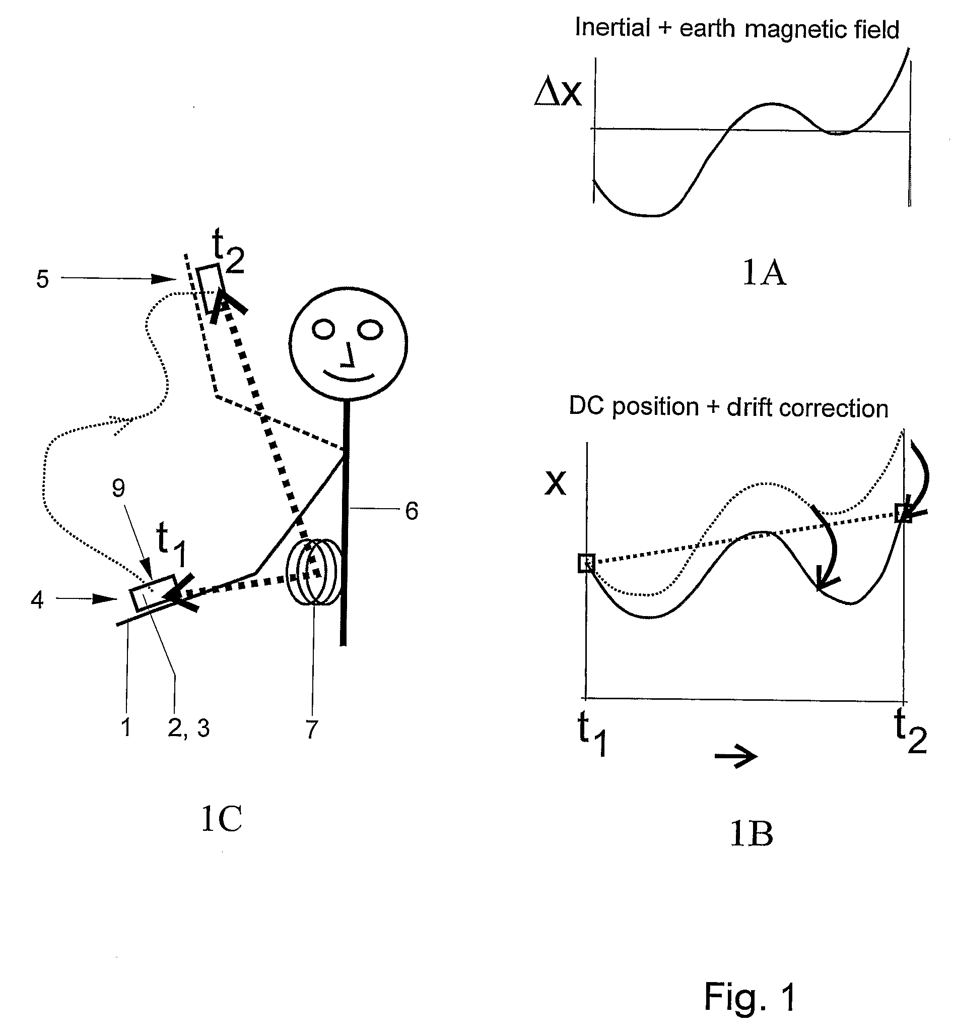
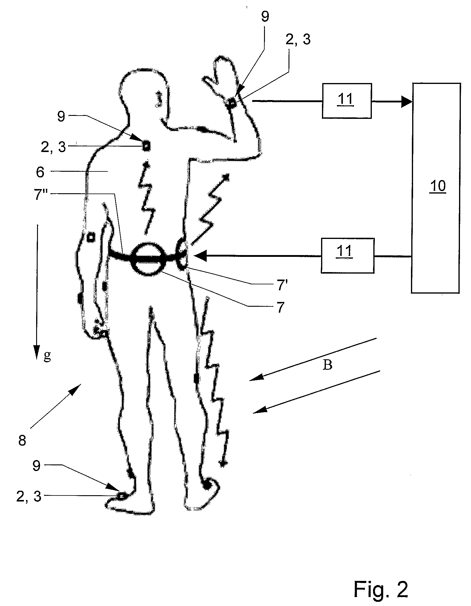
[0011]Thus, at regular intervals, relative position and orientation measurements are carried out with the magnetic field sensor system. This prevents drift in the position estimation based on the acceleration transducers. Further, parameters of a model of the sensors, such as for instance the offset and / or gain of the acceleration transducers, are identified, preferably with the aid of signal-processing methods which enable estimation of stochastic signals, such as Kalman filters. With the aid of the inertial module, orientations can be determined and changes of position, in particular by double integration in time of accelerations after a rotation of the signals to the inertial coordinate system and the subtraction of the gravitational acceleration. Due to this configuration, a relatively low transmitting frequency of the magnetic field transmitters is sufficient, because the output of the magnetic measuring module substantially serves to calibrate the orientation and position information obtained from the inertial module. Thus, the required power can be reduced considerably reducing the weight of the design and so that ambulatory uses can be possible for sufficiently long periods (hours to a day). Further, the system can have a considerably less expensive design than the currently available motion tracking systems.
[0012]In addition, the relative positions and orientation estimations can also be improved by making use of anatomical knowledge of the body and typical motion characteristics.

Problems solved by technology

Thus, relatively much power is required so that, in practice, this system has limited uses.
However, the system makes use of external magnetic field transmitters, which are disadvantageous with ambulatory use.

Method used


Image

  • Motion tracking system
  • Motion tracking system
  • Motion tracking system

Examples


Embodiment Construction

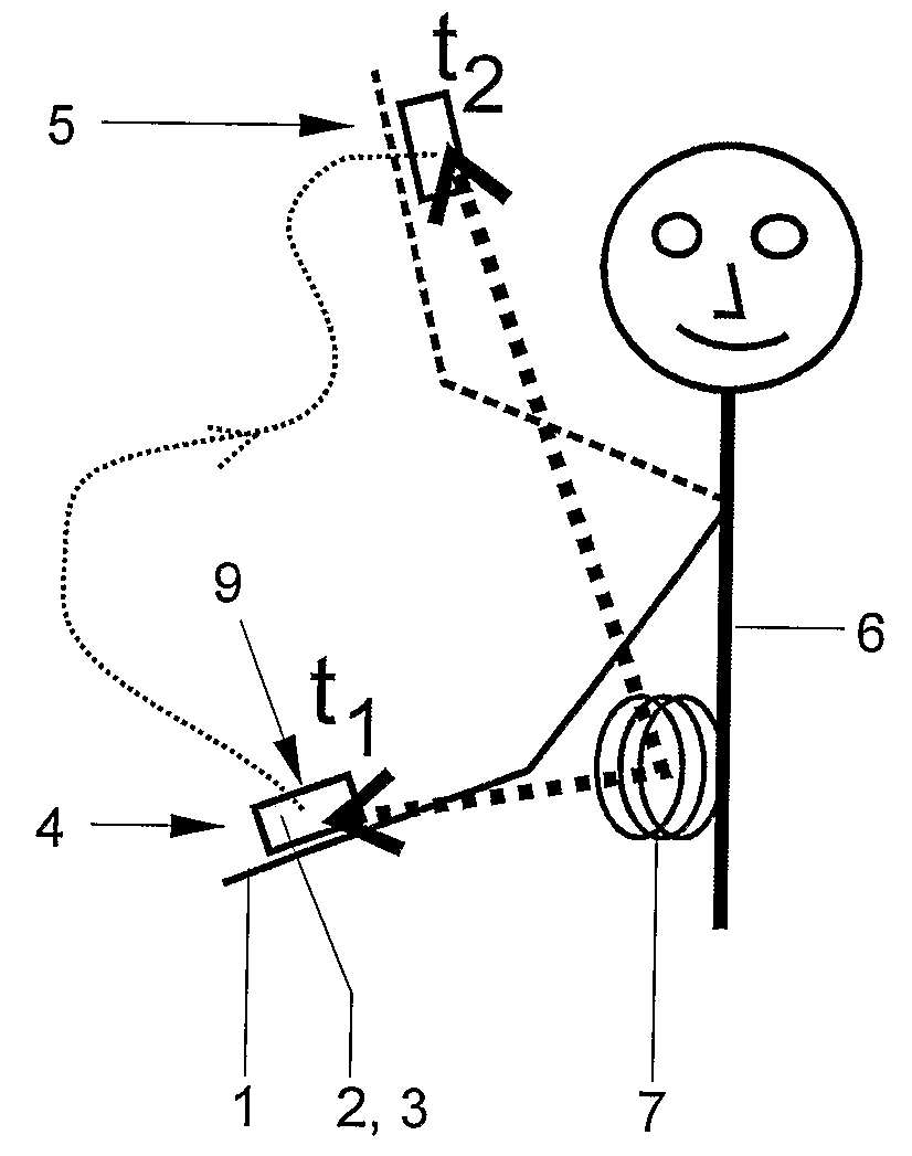
[0022]FIG. 1 shows the principle of combining data coming from an inertial measurement unit, periodically calibrated by data coming from a pulsed magnetic sensor system. To this end, illustration C shows a schematic view of a test subject who moves an arm 1 with a magnetic sensor 2 and an inertial measurement unit 3 thereon from a first position 4 to a second position 5 between the times t1 and t2. On the trunk 6, a magnetic field transmitter 7 is fixed, typically a current coil for generating a magnetic (dipole) field. At both times, as measurement is carried out with the aid of the magnetic system, which particularly comprises magnetic module 2 and magnetic field transmitters 7. These measurements serve to determine the relative positions and orientations of arm 1 at those times t1 and t2 for recalibrating the measurement data coming from the inertial measurement unit 3 (see illustration A). In this manner, the relative positions of a few measuring points provided on the body can ...


PUM


Abstract

A motion tracking system for tracking an object composed of object parts in a three-dimensional space. The system comprises a number of magnetic field transmitters; a number of field receivers for receiving the magnetic fields of the field transmitters; a number of inertial measurement units for recording a linear acceleration; a number of angular velocity transducers for recording angular velocities. The system further comprises a processor for controlling the transmitters and receiving signals coming from the field receivers and the inertial measurement unit; which processor contains a module for deriving orientation and / or position information of the constituent object parts of the object on the basis of the received signals. The processor is configured for intermittently controlling the transmitters transmit at a predetermined frequency, wherein the position and / or orientation information is derived by periodically calibrating the motion information coming from the inertial measurement unit with the motion information coming from the magnetic field receivers.

Description

[0001]The invention relates to a motion tracking system for tracking an object composed of object parts in a three-dimensional space. In particular, the invention relates to a motion tracking system for tracking the movements of a human body.[0002]Measurement of physical motion with a high resolution is important for many medical, sports and ergonomic applications. Further, in the film and computer game market, there is a great need for motion data for the purpose of advanced animation and special effects. Finally, for instance, motion data is needed in Virtual Reality (VR) and Augmented Reality (AR) applications for training and simulation.[0003]At this moment, there are a number of technologies available for tracking and recording motion data. They generally require that an infrastructure be constructed around the object to be tracked. An example thereof are optical systems which use a large number of cameras, fixedly arranged around the object of which the motion is to be tracked...

Claims


Application Information

Patent Timeline
IPC IPC(8): G09G5/00
CPCA61B5/103A61B5/1114A61B2560/0223A61B5/6804A61B5/6807A61B5/1127
Inventor SLYCKE, PER JOHANVELTINK, PETRUS HERMANUSROETENBERG, DANIEL
Owner XSENS HLDG BV
Learn More