Exhaust emission control system for internal combustion engine

Inactive Publication Date: 2009-11-19
HONDA MOTOR CO LTD
View PDF8 Cites 8 Cited by
  • Summary
  • Abstract
  • Description
  • Claims
  • Application Information

AI Technical Summary

Benefits of technology

[0006]The present invention is achieved in view of these circumstances, and has an object to provide an exhaust emission control system for an internal combustion engine that allows secondary air to be supplied into an exhaust passa

Problems solved by technology

Thus, even if the exhaust emission control system disclosed in the above-described Japanese Utility Model Registration No. 2535339 is employed, the one-way valve in the secondary air passage is not opened, and secondary air cannot be supplied to the exhaust passage

Method used


Image

  • Exhaust emission control system for internal combustion engine
  • Exhaust emission control system for internal combustion engine
  • Exhaust emission control system for internal combustion engine

Examples


first embodiment

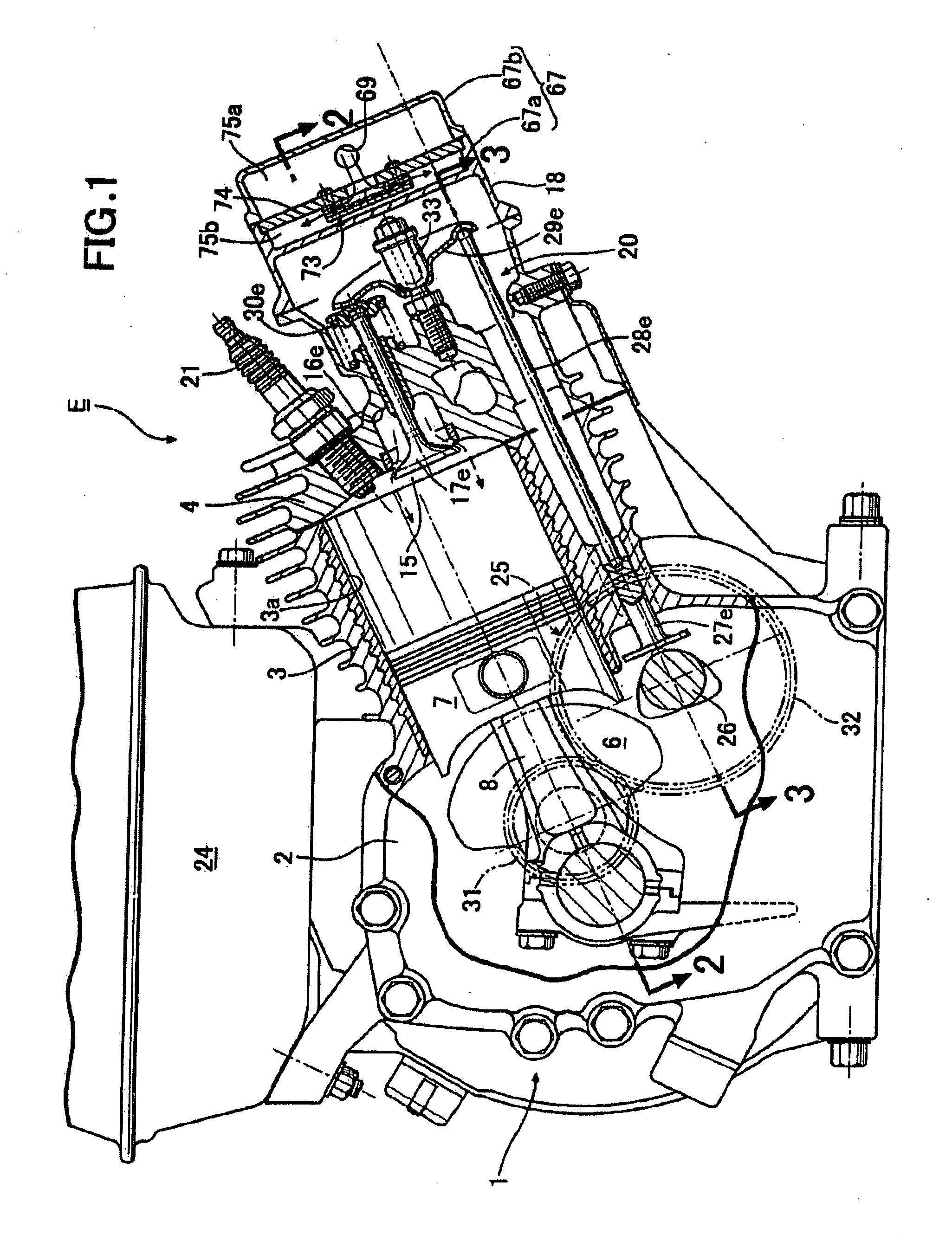
[0026]the present invention will be explained below based on FIGS. 1 to 10.

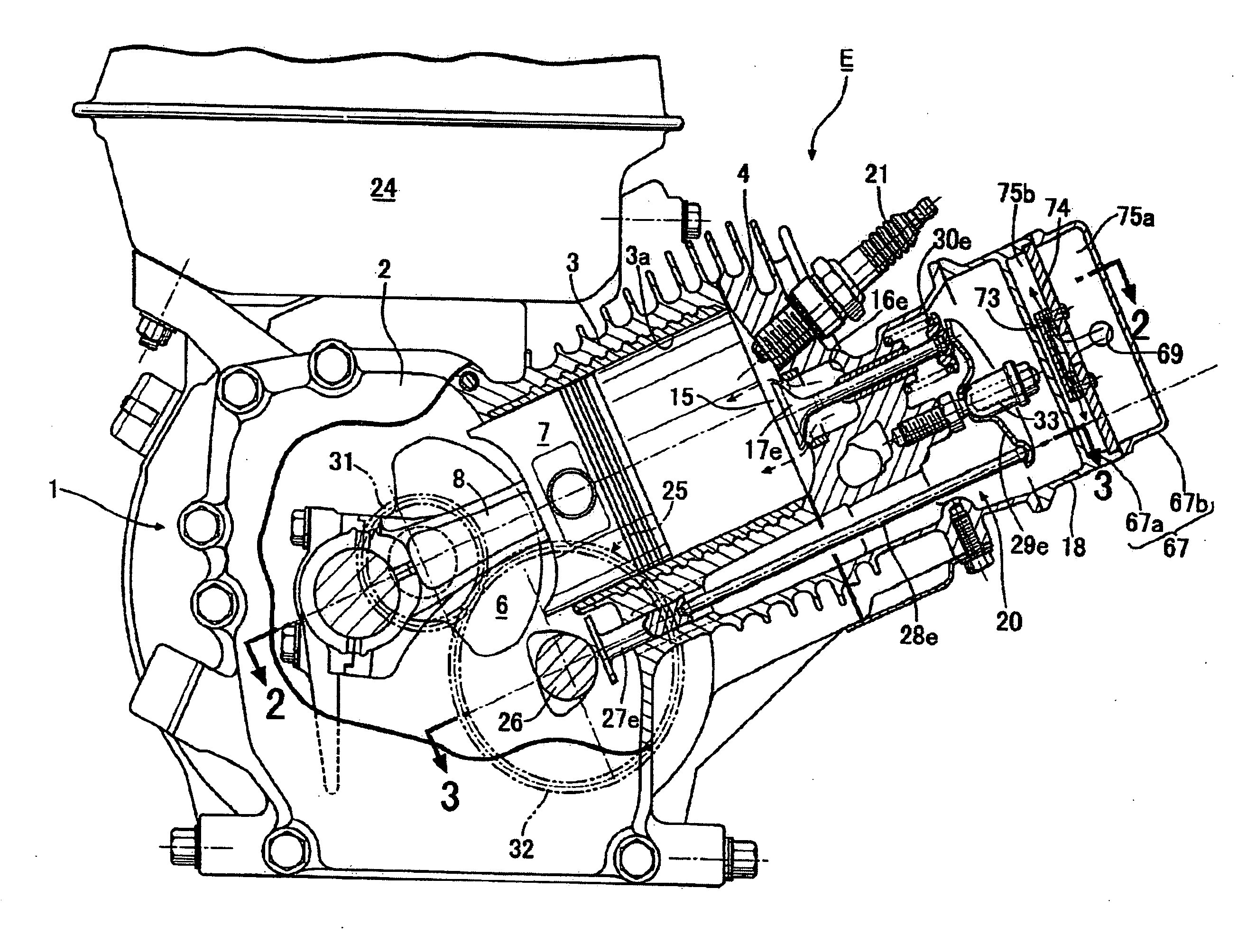
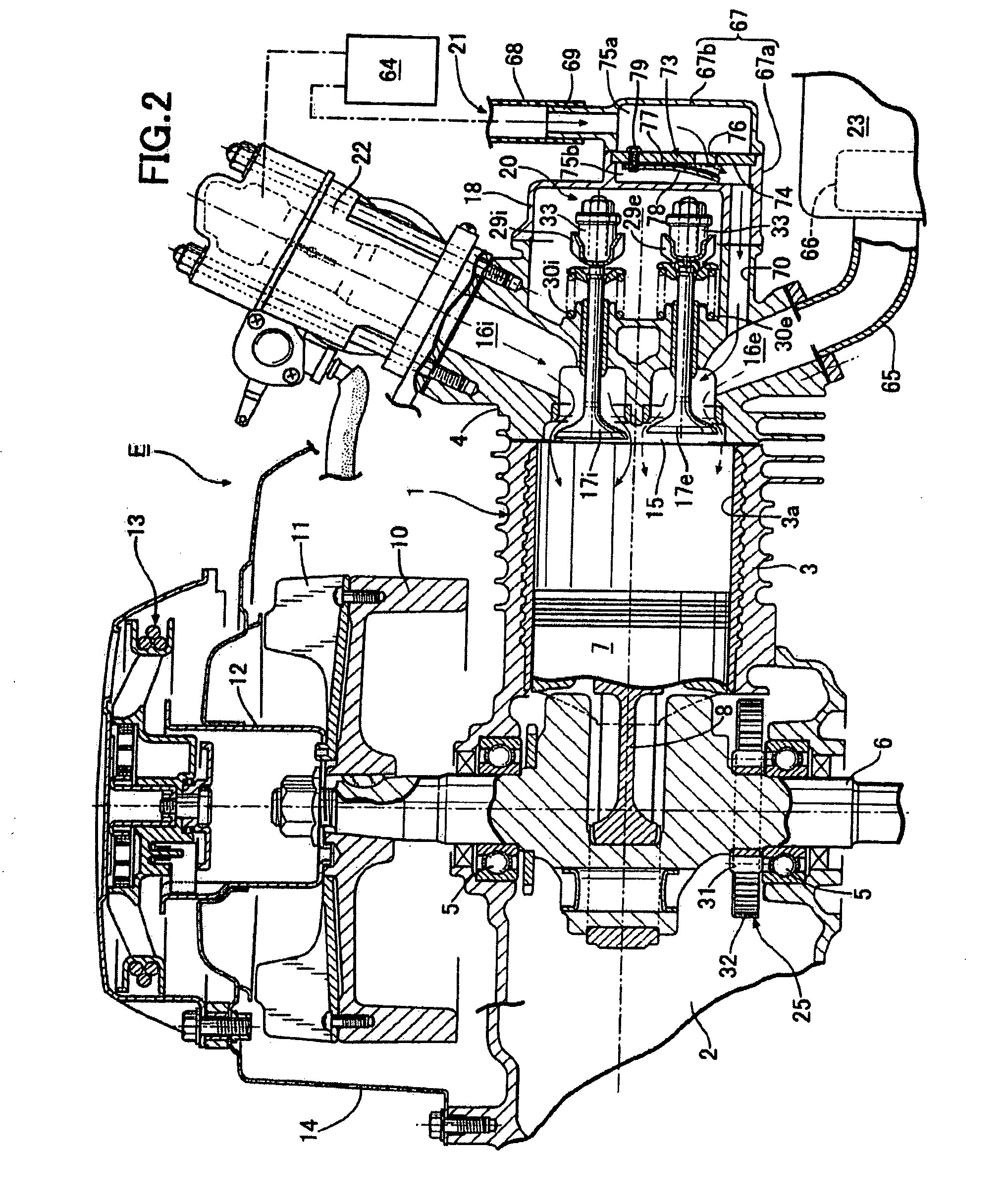
[0027]In FIGS. 1 to 3, an engine body 1 of an internal combustion engine E comprises a crankcase 2, a cylinder block 3 extending obliquely upward from one side of the crankcase 2, and a cylinder head 4 joined to an upper end surface of the cylinder block3. The crankcase 2 houses a crankshaft 6 supported on left and right sidewalls thereof via bearings 5 and 5. The crankshaft 6 is connected to a piston 7 fitted in a cylinder bore 3a of the cylinder block 3 via a connecting rod 8. A flywheel 10 is secured to one end of the crankshaft 6 protruding outside the crankcase 2. An annular cooling fan 11 is secured to an outer side surface of the flywheel 10. A starting cylinder shaft 12 protruding axially outward from the cooling fan 11 is secured on a center of the flywheel 10. A known recoil starter 13 that can engage the starting cylinder shaft 12 to crank the crankshaft 6 is mounted to the crankcase 2 via a bracke...


PUM


Abstract

In an exhaust emission control system for an internal combustion engine, an exhaust gas recirculation device that operates so as to partially open an exhaust valve to introduce exhaust gas into a cylinder in an intake stroke is provided; a secondary air passage capable of supplying secondary air to an exhaust passage is connected to the exhaust passage; and a one-way valve opened by negative pressure applied from the cylinder to the exhaust passage following an operation of the exhaust gas recirculation device in the intake stroke is provided in the secondary air passage. Accordingly, it is possible to provide an exhaust emission control system for an internal combustion engine that allows secondary air to be supplied into an exhaust passage to reduce HC and CO concentrations and also a NOx concentration in an exhaust gas without using an air pump regardless of an exhaust system structure of the internal combustion engine.

Description

BACKGROUND OF THE INVENTION[0001]1. Field of the Invention[0002]The present invention relates to an exhaust emission control system for an internal combustion engine which supplies secondary air into an exhaust passage to oxidize and remove HC and CO in an exhaust gas, and which introduces an exhaust gas into a cylinder in an intake stroke to prevent generation of NOx during combustion.[0003]2. Description of the Related Art[0004]Japanese Utility Model Registration No. 2535339 discloses an exhaust emission control system for an internal combustion engine including: a secondary air passage connected to an exhaust passage; and a one-way valve that is provided in the secondary air passage and opened by negative pressure by exhaust pulsation in an exhaust stroke in order to supply secondary air into the exhaust passage to oxidize and remove HC and CO in an exhaust gas. Japanese Patent Application Laid-Open No. 2005-240793 also discloses an exhaust emission control system for an internal...

Claims


Application Information

Patent Timeline
IPC IPC(8): F01N3/02F02M25/07
CPCF01L13/08F01L13/085F01N3/22F01N3/34F01N2430/10Y02T10/20F02D13/0273F02D13/04F02M25/0752Y02T10/121F02D13/0246F02M26/01Y02T10/12
Inventor KASHIMA, SOJI
Owner HONDA MOTOR CO LTD
Why Eureka
Try Eureka