System and method for monitoring blue-green algae in a fluid

a fluid and blue-green algae technology, applied in the field of flow analysis configuration, can solve the problems of insufficient detection efficiency, inconclusive resolution, insufficient etc., and achieve the effects of high resolution, enhanced blue-green algae detection accuracy, and enhanced sensitivity

Inactive Publication Date: 2009-11-19
FLUID IMAGING TECH
View PDF9 Cites 18 Cited by
  • Summary
  • Abstract
  • Description
  • Claims
  • Application Information

AI Technical Summary

Benefits of technology

[0007]It is an object of the present invention to provide a system arranged to detect with reliable accuracy the existence of blue-green algae in a fluid. It is also an object of the present invention to provide such a system that may be incorporated into, or operate in a similar manner as that of, existing detection system including, but not limited to, imaging flow cytometers.
[0008]These and other objects are achieved with the present invention, which is a cytometer system with a detection mechanism that includes detectors configured to detect two different ranges of fluorescence produced by particles, including blue-green algae particles, in the fluid flowing through the flow chamber. Each of the detectors is arranged to generate a trigger signal whenever fluorescence is detected. Also, the system includes an arrangement that permits particles much larger in size to pass through the field of view than permitted by current flow cytometry systems. This ensures more accurate blue-green algae detection as more particles actually in the fluid under evaluation will be delivered into the field of view. It is to be noted that the length and width of the channel of the chamber are preferably selected to roughly match the field of view of the imaging and fluorescence optics used to detect the particles. The system further optionally includes a video system arranged to image particles in the fluid in the flow chamber in response to the trigger signals. Images captured by the video system are of high resolution and may be used in comparison to known blue-green algae images of a library of images. Computer programming is created to operate a computing device of the system to distinguish particles in the fluid based on different fluore

Problems solved by technology

Unfortunately, that capability is not satisfactory as the blue-green algae cannot be detected before it becomes a noticeable problem.
The inefficiencies of detecting blue-green algae with existing bulk monitoring and conventional flow cytometry systems produce inconclusive resolution resulting from less than optimum collection of fluorescence emissions from a fluid samp

Method used


Image

  • System and method for monitoring blue-green algae in a fluid
  • System and method for monitoring blue-green algae in a fluid
  • System and method for monitoring blue-green algae in a fluid

Examples


Embodiment Construction

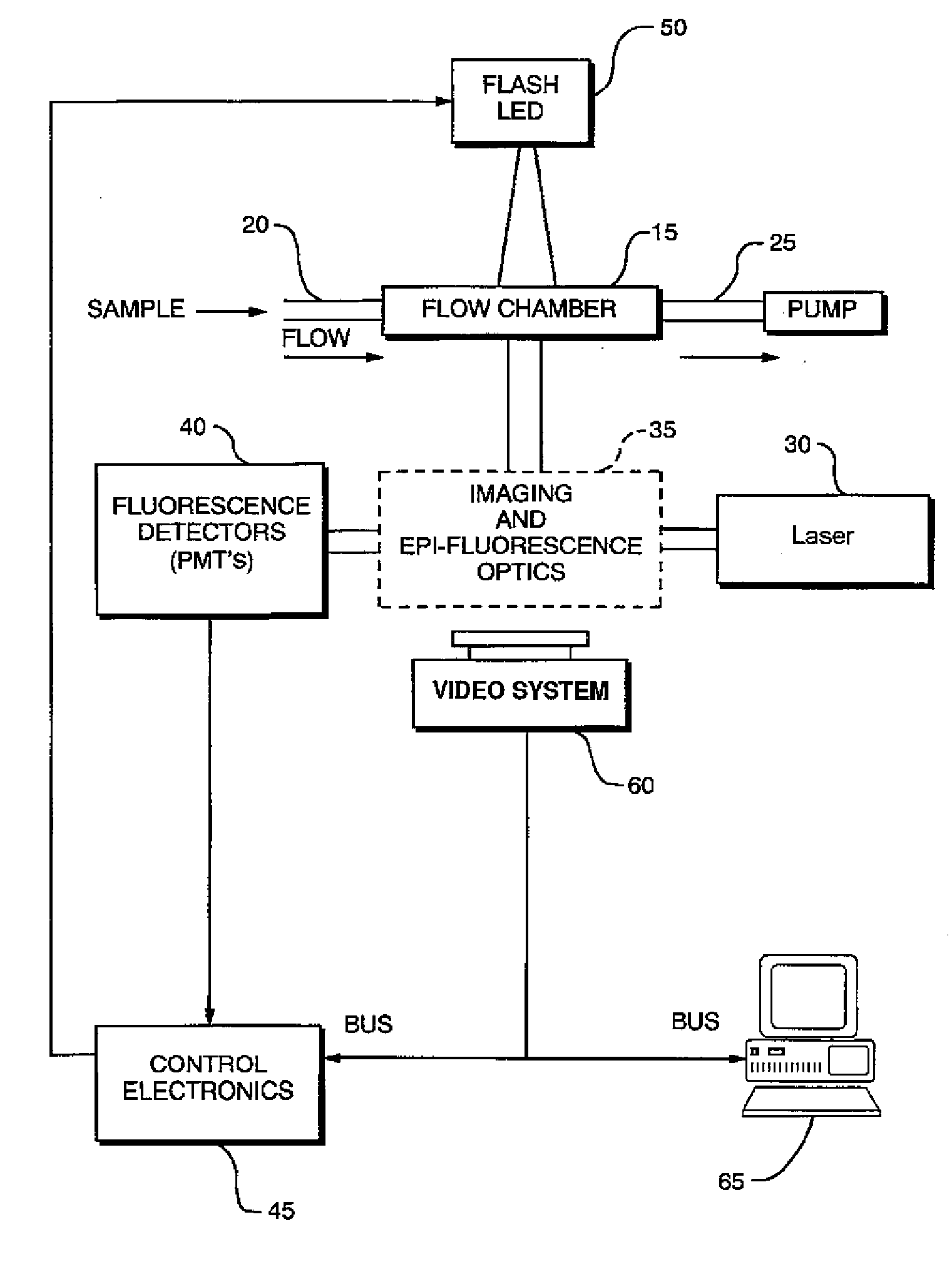
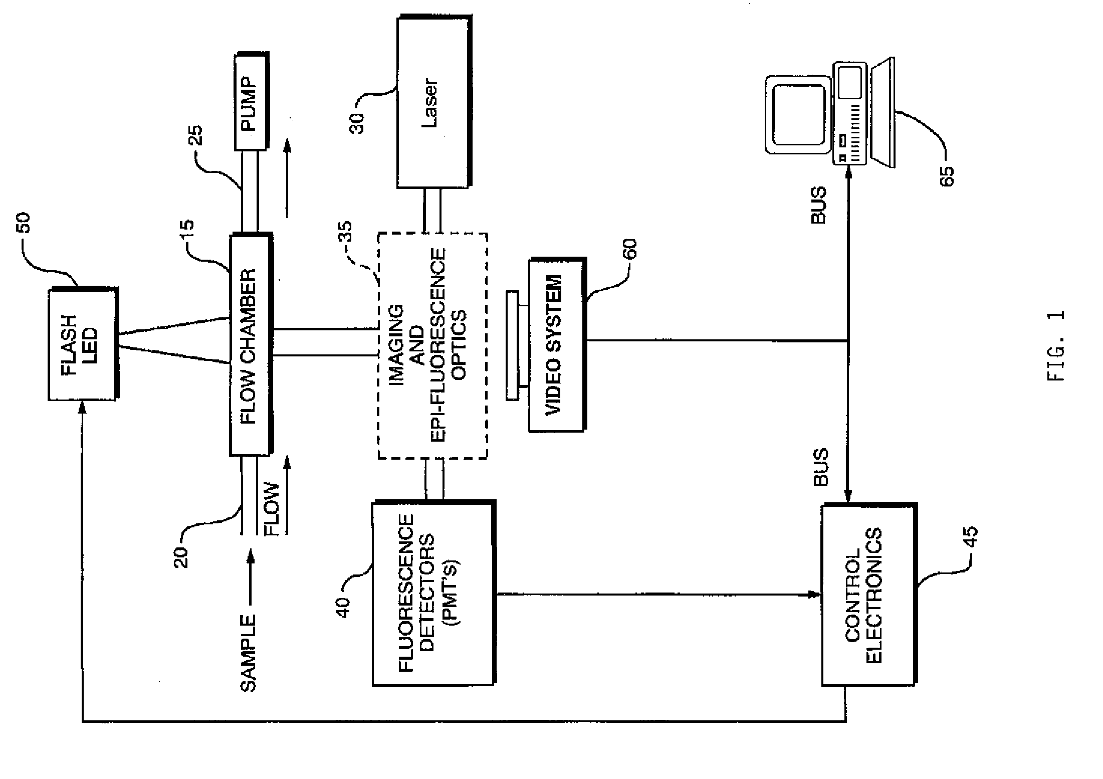
[0015]A system 10 of the present invention suitable for high quality automated counting and imaging of particles that exist in a fluid is shown in FIGS. 1 and 2. The system 10 of the present invention is similar in manner to the flow cytometer described in U.S. Pat. No. 6,115,119 entitled “Device And Method For Studying Particles In A Fluid,” issued Sep. 5, 2000, the entire content of which is incorporated herein by reference. The system 10 includes a flow chamber 15, a light source 30, imaging and fluorescence optics 35, an image detection system 40, a backlighting generator 50, an optional image capturing system 60 and a computing device 65. The combination of these components of the system 10 arranged and configured as described herein enable a user to detect particles in the fluid, including blue-green algae particles in the fluid and, specifically, to enhance the accuracy and sensitivity of such detection.

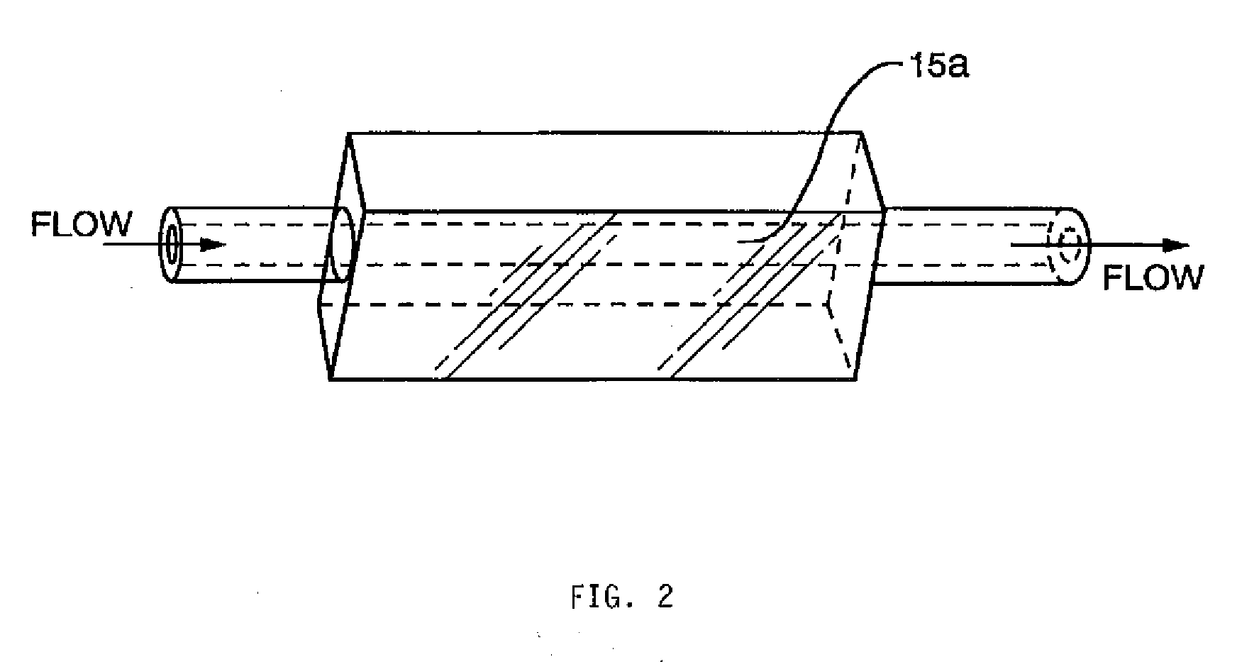
[0016]The flow chamber 15 includes an inlet 20 for receiving the particle...


PUM


Abstract

A particle detection system with a detection mechanism that includes detectors positioned to detect two different ranges of fluorescence produced by particles in the fluid in a flow chamber. Each of the detectors is arranged to generating a trigger signal whenever fluorescence is detected. The system and related method enhance the accuracy and sensitivity of blue-green algae monitoring by utilizing imaging flow cytometry combined with particle analysis and the measurement of the ratio of each particle's phycocyanin to chlorophyll b detected by using the two detectors configured for detection of two different fluorescence ranges, one associated with the phycocyanin and the other associated with the chlorophyll b. Optionally, captured images may be used in comparison to known images of a library of images.

Description

BACKGROUND OF THE INVENTION[0001]1. Field of the Invention[0002]The present invention relates generally to a flow analysis configuration used in particle analysis instrumentation, and more particularly to a flow analysis system configured to enable the accurate identification of the existence of blue-green algae in a fluid. The system may include an optical imaging capability.[0003]2. Description of the Prior Art[0004]The art has seen various optical / flow systems employed for transporting a fluid within an analytical instrument to an imaging and optical analysis area. A liquid sample is typically delivered into the bore of a flow chamber and this sample is interrogated in some way so as to generate analytical information concerning the nature or properties of the sample. For example, a laser beam may excite the sample that is present in the bore of the capillary, with the emitted fluorescence energy representing the signal information.[0005]In the area of identifying specific partic...

Claims


Application Information

Patent Timeline
IPC IPC(8): G21K5/00G01N15/02
CPCG01N15/1459G01N15/1434G01N21/6486
Inventor SIERACKI, CHRISTIAN K.PETERSON, KENT A.NELSON, WILLIAM H.
Owner FLUID IMAGING TECH
Why Eureka
Try Eureka