PRODUCTION METHOD OF TITANIUM DIOXIDE (TiO2) PHOTOCATALYST AND TiO2 PHOTOCATALYST PRODUCED BY THE SAME

a technology of titanium dioxide and photocatalysts, which is applied in the direction of physical/chemical process catalysts, metal/metal-oxide/metal-hydroxide catalysts, etc., can solve the problems of short wavelength ultraviolet (uv) light, poor reactivity of titanium dioxide photocatalysts, and relatively short holes. , to achieve the effect of improving surface characteristics and high mesoporosity

Inactive Publication Date: 2009-11-19
KYUNGPOOK NAT UNIV IND ACADEMIC COOP FOUND
View PDF7 Cites 36 Cited by
  • Summary
  • Abstract
  • Description
  • Claims
  • Application Information

AI Technical Summary

Benefits of technology

[0007]The present invention has been made in an effort to solve the above problems, and it is one object of the present invention to provide a method for producing a titanium dioxide photocatalyst with high mesoporosity and improved surface characteristics by which an anatase structure is formed upon drying and is maintained stable even at high temperatures.

Problems solved by technology

A disadvantage associated with the use of titanium dioxide as a photocatalyst is that light of short wavelengths in the ultraviolet (UV) region is required.
However, the reactivity of the titanium dioxide photocatalysts is known to be poor due to the possibility that the time when electrons and holes separately exist may be relatively short depending on the kind and amount of metals used in comparison with pure titanium dioxide.

Method used


Image

  • PRODUCTION METHOD OF TITANIUM DIOXIDE (TiO2) PHOTOCATALYST AND TiO2 PHOTOCATALYST PRODUCED BY THE SAME
  • PRODUCTION METHOD OF TITANIUM DIOXIDE (TiO2) PHOTOCATALYST AND TiO2 PHOTOCATALYST PRODUCED BY THE SAME
  • PRODUCTION METHOD OF TITANIUM DIOXIDE (TiO2) PHOTOCATALYST AND TiO2 PHOTOCATALYST PRODUCED BY THE SAME

Examples


example 1

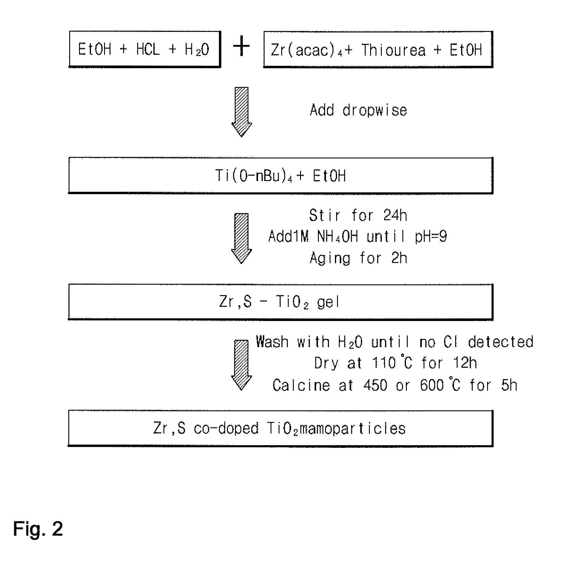
[0074]A titanium dioxide photocatalyst was produced using a sol-gel process in which an acid and a base were added in two separate steps in accordance with the following procedure:

[0075](1) Tetrabutyl orthotitanate (Ti(O-nBu)4, 21.3 mL, 62.5 mmol) was dissolved in ethanol (140 ml) to prepare a solution of the Ti(O-nBu)4.

[0076](2) Distilled water (22.0 mL, 1.2 mol) and an aqueous hydrochloric acid solution (6.0 mL, 0.20 mol) were added to ethanol (70 mL) to prepare a solution (“Solution A”). Solution A was added dropwise to the Ti(O-nBu)4 solution with stirring until pH 0.8. After completion of the addition, stirring was continued at room temperature for 24 hours.

[0077](3) 1 M NH4OH solution was added dropwise to the mixed solution with stirring until pH 9.0. The resulting solution was gradually converted to a gel. After the gel was observed, aging was performed for 2 hours, followed by filtration to remove the remaining solution. The filtered gel was washed with distilled water to r...

example 2

[0080]Zirconium acetylacetonate (Zr(acac)4, 0.15 g, 0.30 mmol) and thiourea (2.38 g, 31.25 mmol) were added to ethanol (70 mL) to prepare a solution (“Solution B”). The procedure of Example 1 was repeated except that Solution B and Solution A were added dropwise in step (2) of Example 1 to produce 0.5Zr,S—TiO2. In the photocatalyst, zirconium was doped in an amount of 0.5 parts by weight, based on 100 parts by weight of titanium dioxide.

example 3

[0081]1Zr,S—TiO2 was produced in the same manner as in Example 2 except that the amount of the zirconium source was changed. In the photocatalyst, zirconium was doped in an amount of one part by weight based on 100 parts by weight of titanium dioxide.


PUM

PropertyMeasurementUnit
reaction timeaaaaaaaaaa
pHaaaaaaaaaa
temperatureaaaaaaaaaa

Abstract

A method for producing a titanium dioxide photocatalyst is provided. The method uses a sol-gel process wherein acid and base catalysts are added in two separate steps. According to the method, a titanium dioxide photocatalyst with increased mesoporosity can be produced without the use of any particular additive. Further, an anatase structure is formed upon drying and is maintained even after high-temperature calcination. Further provided is a titanium dioxide photocatalyst produced by the method. Further provided is a titanium dioxide photocatalyst doped with sulfur and zirconium, which is produced by using the method. The doped titanium dioxide photocatalyst exhibits catalytic activity even under visible light and excellent surface characteristics to achieve improved photocatalytic activity.

Description

BACKGROUND OF THE INVENTION[0001]1. Field of the Invention[0002]The present invention relates to a method for producing a titanium dioxide (TiO2) photocatalyst and a titanium dioxide photocatalyst produced by the method. More specifically, the present invention relates to a method for producing a titanium dioxide photocatalyst using a sol-gel process wherein an acid and a base are added in two separate steps to achieve high mesoporosity and improved surface characteristics while maintaining an anatase crystal structure even at high temperatures, and a titanium dioxide photocatalyst produced by the method. The present invention also relates to a titanium dioxide photocatalyst doped with sulfur and zirconium that possesses catalytic activity even in the visible region, and exhibits excellent surface characteristics in terms of surface area, pore size, pore volume, etc. and improved catalytic activity.[0003]2. Description of the Related Art[0004]Since Honda and Fujishima of Tokyo Unive...

Claims


Application Information

Patent Timeline
Patent Type & Authority Applications(United States)
IPC IPC(8): B01J21/06C01G23/08
CPCB01J21/063C01P2006/17B01J35/004B01J37/033B82Y30/00C01G23/053C01P2002/72C01P2002/77C01P2002/82C01P2002/85C01P2004/04C01P2004/64C01P2006/12C01P2006/14C01P2006/16B01J21/066B01J21/06B01J37/08
Inventor KIM, TAE JEONGKIM, WHA JUNGKIM, SUN WOO
Owner KYUNGPOOK NAT UNIV IND ACADEMIC COOP FOUND
Why Eureka
Try Eureka