Self-Biased Phase Locked Loop

a phase locking loop and self-biased technology, applied in the direction of electrical equipment, pulse automatic control, etc., can solve the problems of increasing the complexity of the circuit design, and achieve the effect of simplifying the circuit design the parameter configuration of the self-biased pll

Active Publication Date: 2009-11-26
SEMICON MFG INT (SHANGHAI) CORP
View PDF3 Cites 9 Cited by
  • Summary
  • Abstract
  • Description
  • Claims
  • Application Information

AI Technical Summary

Benefits of technology

[0018]Compared with the prior art, the currents output from the two charge pumps are different. The current output from the first charge pump for discharging and charging the capacitor is proportional to the bias voltage of the VCO and is inversely proportional to the frequency division factor of the frequency divider. The current output from the second charge pump for discharging and charging the resistance is proportional to the bias voltage of the VCO and is independent of the frequency division factor of the frequency divider. Thus, the second charge pump ca

Problems solved by technology

Therefore, the complexity of t

Method used


Image

  • Self-Biased Phase Locked Loop
  • Self-Biased Phase Locked Loop
  • Self-Biased Phase Locked Loop

Examples


Embodiment Construction

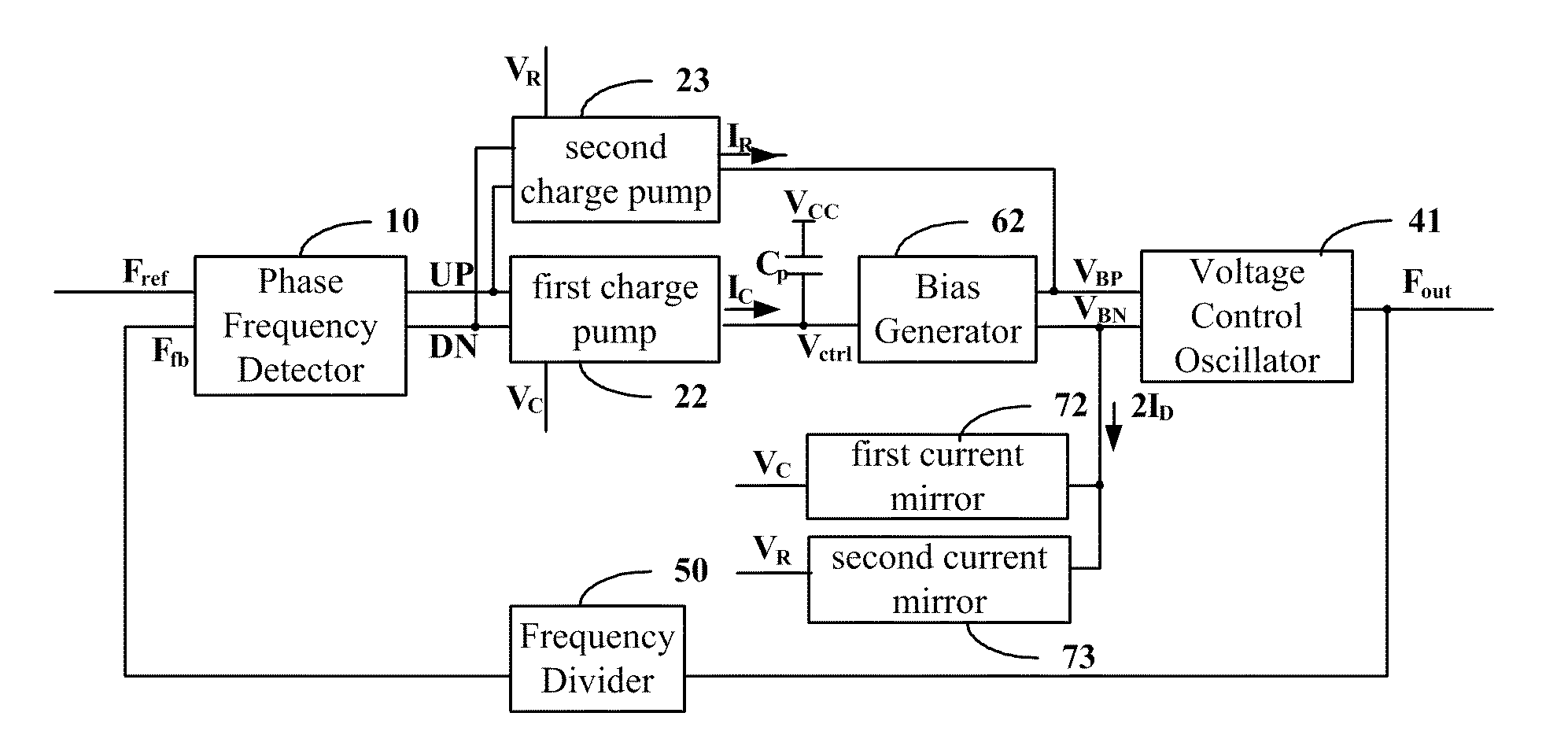
[0026]According to one embodiment of the present invention, two charge pumps are configured to output different currents, so that the parameter x in formulas 3) and 4) is inversely proportional to the frequency division factor N and the parameter y is proportional to the frequency division factor N. Therefore, the frequency division factor N in the formulas may be eliminated without incorporating a new parameter and the ratio of the loop bandwidth ωn to the input frequency ωref and the damping factor ξ which are independent of the frequency division factor N may be obtained.

[0027]The above conclusion that different currents output from two charge pumps can eliminate the frequency division factor N in the formulas 3) and 4) is obtained for the following reasons.

ΔVctrl=Δφ×Ip2π×(Rp+1sCp)5)

The formula 5) is adapted to calculate the control voltage across the loop filter in the conventional charge pump PLL, where, ΔVctrl is the control voltage across the loop filter caused by the current...


PUM


Abstract

A self-biased PLL includes a first charge pump and a second charge pump, an output terminal of the first charge pump is connected with a discharge-charge capacitor to output a control voltage, an output terminal of the second charge pump is connected with an output terminal of a bias generator for outputting a first bias voltage equal to the control voltage, wherein, a current output from the first charge pump is equal to a value obtained through dividing the production of a first constant with a bias current of a voltage control oscillator by a frequency division factor of a frequency divider; a current output from the second charge pump is equal to a value obtained through dividing the bias current of the voltage control oscillator by a second constant; and a multiple relation exists between an output resistance of the bias generator and an equivalent resistance of a differential buffer delay stage in the voltage control oscillator.

Description

FIELD OF THE INVENTION[0001]The present invention relates to the phase locked loop (PLL) and in particular, to a self-biased PLL.BACKGROUND OF THE INVENTION[0002]The PLL is widely used in System on Chip (SOC) to construct a frequency synthesizer, a clock generator and so on. FIG. 1 shows a basic structure of a PLL. In FIG. 1, the phase frequency detector (PFD) 10 detects the frequency difference and the phase difference between the input signal Fref and the feedback signal Ffb and generates and inputs pulse control signals UP and DN to the charge pump 20. In the charge pump 20, the pulse control signals UP and DN are converted into current IP so as to discharge and charge the capacitor Cp in the loop filter 30. The loop filter 30 generates the control voltage Vctrl and input the control voltage Vctrl to the voltage control oscillator (VCO) 40. The VCO 40 increases the oscillation frequency when the control voltage Vctrl increases and decreases the oscillation frequency when the cont...

Claims


Application Information

Patent Timeline
IPC IPC(8): H03L7/00
CPCH03L7/0893H03L7/0995H03L7/093H03L7/0898
Inventor PENG, JINZHONGFU, ZHIGANG
Owner SEMICON MFG INT (SHANGHAI) CORP
Why Eureka
Try Eureka