Fluorescent substance and process for producing the same

a technology of fluorescent substances and processes, applied in non-linear optics, lighting and heating apparatuses, instruments, etc., to achieve excellent light-emitting properties, increase light-emitting intensity, and high intensity

Inactive Publication Date: 2009-11-26
SHOWA DENKO KK
View PDF3 Cites 1 Cited by
  • Summary
  • Abstract
  • Description
  • Claims
  • Application Information

AI Technical Summary

Benefits of technology

[0029]Moreover, the lamp which uses the fluorescent substance in accordance with the present invention can convert the light-emitting wavelength of an LED as a primary light source into a secondary light-emitting wavelength, by the constitutions (11) and (12) in the above, thereby providing a wavelength-converting type lamp having a large light-emitting intensity which can emit light with an arbitrary color tone.
[0030]In accordance with the fluorescent substance of the present invention and the process for producing the same, because of the constitutions and effects in the above, it is possible to make a secondary light-emitting wavelength of a fluorescent substance a wavelength of an arbitrary color tone and increase the light-emitting intensity.
[0031]Thereby it is possible to obtain light having high intensity and excellent light-emitting properties with an arbitrary color tone, by using one or more kinds of fluorescent substances, even if the primary light-emitting wavelength from an LED is the same wavelength.
[0032]Therefore, a lamp having high brightness, long life, small size, and excellent general-purpose properties can be provided at a low cost.
[0033]Since the lamp which uses the fluorescent substance of the present invention excels in general-purpose properties, it can be used for various uses such as a display, an LCD backlight, a white LED, an LED for use in illumination; in particular, high efficiency can be provided in the case of using the lamp as a white LED lamp.

Problems solved by technology

However, the lamp which uses the fluorescent substance disclosed in Patent document 1 fails to possess the light-emitting intensity of the secondary one sufficiently, and it is necessary to substitute a part of the component composition of a YAG:Ce fluorescent substance in order to convert the light-emitting wavelength (excitation wavelength) into an arbitrary band.

Method used


Image

  • Fluorescent substance and process for producing the same
  • Fluorescent substance and process for producing the same
  • Fluorescent substance and process for producing the same

Examples


example 1

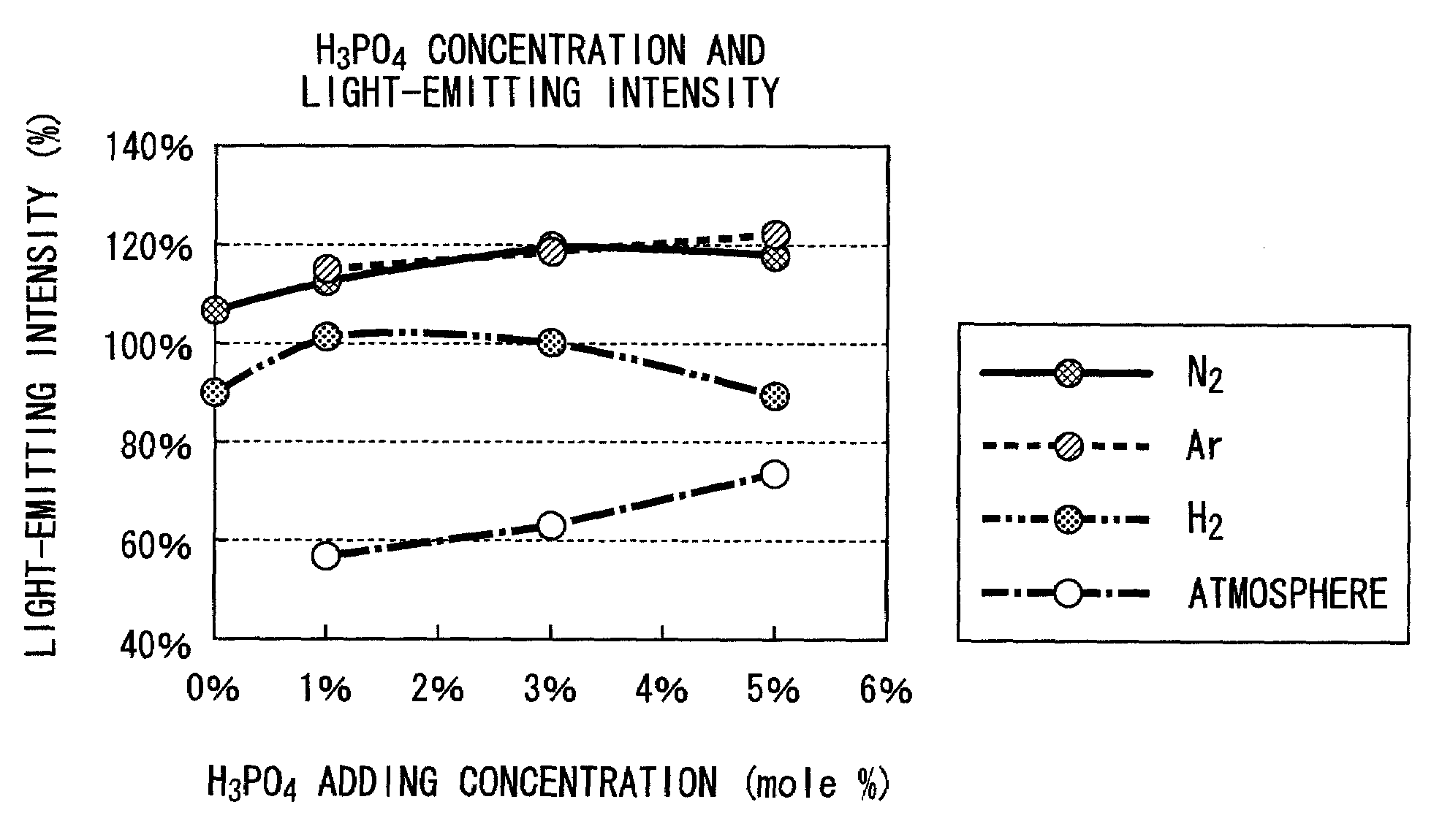
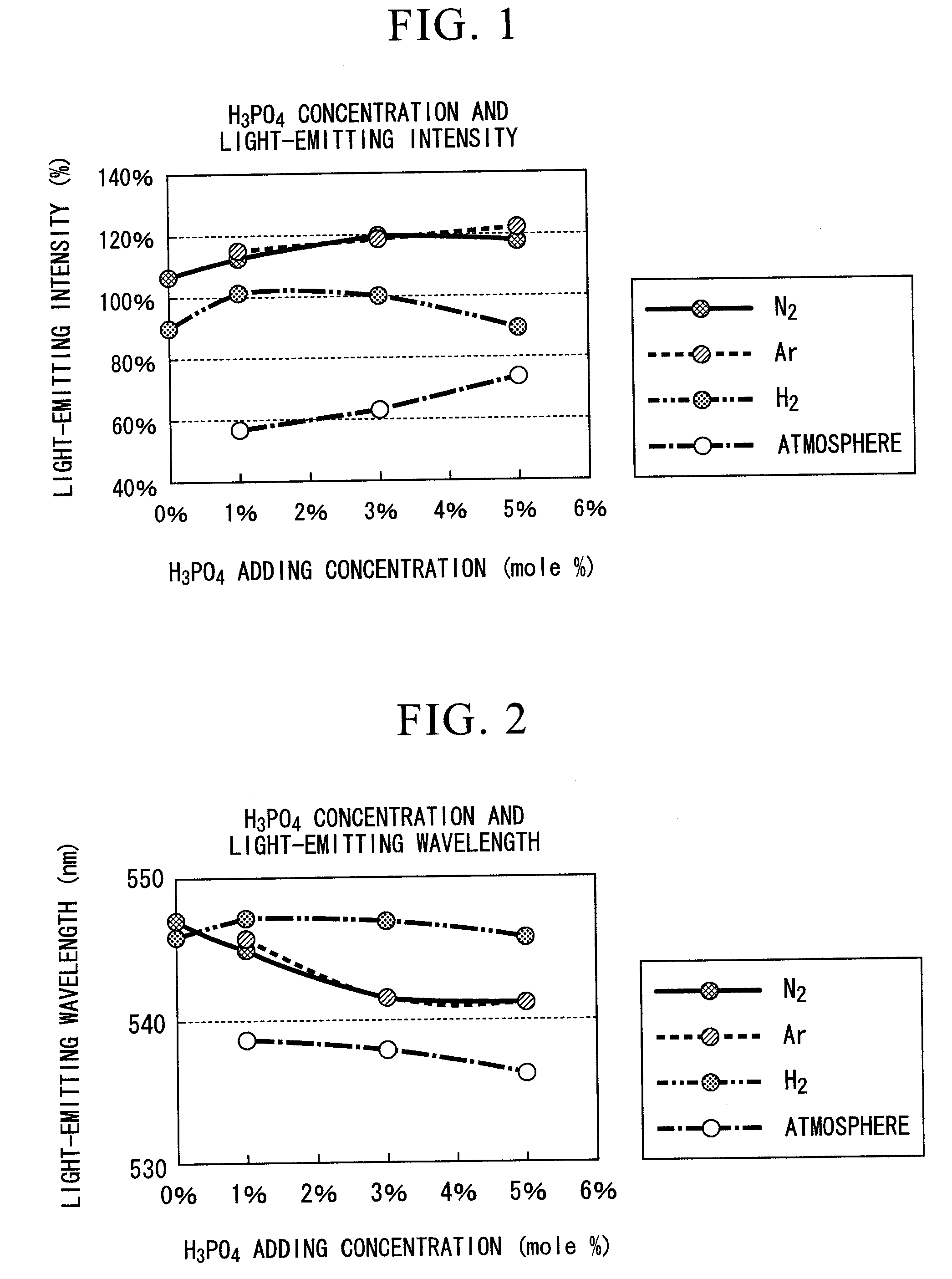
[0079]FIGS. 1 and 2 are graphs which show the relative intensity (light-emitting intensity) of the maximum light-emitting peak height, and the wavelength (light-emitting wavelength) of the maximum light-emitting peak height of the fluorescent substance which was synthesized by compounding each of Y2O3, Al2O3 and CeO2 so as to be Y2.91Ce0.09Al5O12, and adding H3PO4 as an element of group V to this, while varying the additive amount and calcining atmosphere.

[0080]As an atmosphere for calcining of the data shown in FIGS. 1 and 2, approximately 100% gas was used respectively in each of “Ar” and “N2”, a mixed gas consisting of 4% of hydrogen and 96% of nitrogen was used in “H2”, and an atmospheric air was used in “Atmosphere” for calcining.

[0081]As a fluorescent substance for comparison, TYPE: KX692B made by KASEI OPTO Co., Ltd. was used. This fluorescent substance is one which has the largest light-emitting intensity in all of commercially available fluorescent substances, having a ligh...

example 2

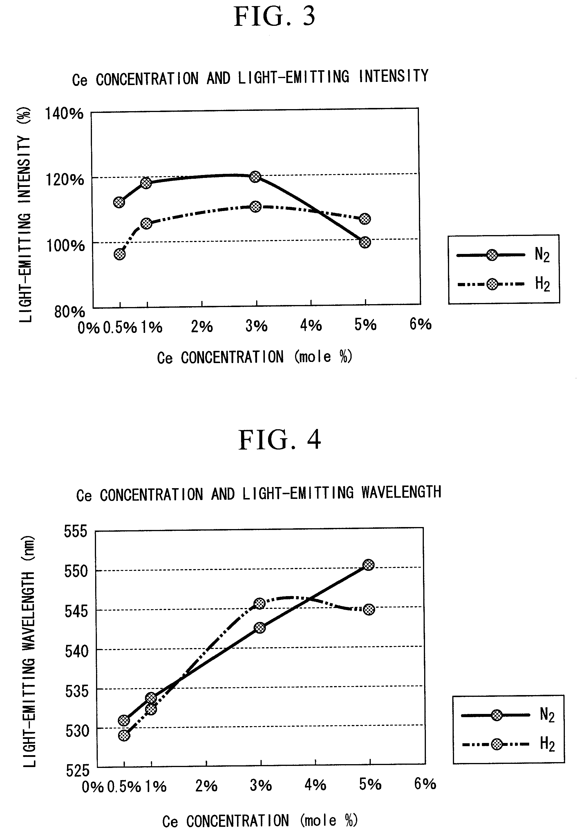
[0089]FIGS. 3 and 4 are graphs which show the relative intensity (light-emitting intensity) of the maximum light-emitting peak height, and the wavelength (light-emitting wavelength) of the maximum light-emitting peak height of the fluorescent substance which was synthesized by compounding each of Y2O3, Al2O3 and CeO2 so as to be Y(3-X)CeXAl5O12, and adding a predetermined amount of 3 mole % of H3PO4 as an element of group V to this, while varying the CeO2 concentration x (mole %) and calcining atmosphere.

[0090]As an atmosphere for calcining of the data shown in FIGS. 3 and 4, approximately 100% gas was used in “N2”, and a mixed gas consisting of 4% of hydrogen and 96% of nitrogen was used in “H2”.

[0091]As a fluorescent substance for comparison, TYPE: KX692B made by KASEI OPTO Co., Ltd. was used, the same as in Example 1.

[0092]The correlation between the CeO2 (Ce) concentration in the state in which H3PO4 was added to the fluorescent substance, and the light-emitting intensity is sho...

example 3

[0100]FIG. 5 is a graph which shows the correlation between the concentration of P which was added during synthesizing the fluorescent substance raw material and the concentration of P contained in the fluorescent substance after the fluorescent substance was synthesized, in the case of synthesizing a fluorescent substance by compounding each of Y2O3, Al2O3 and CeO2 so as to be Y2.91Ce0.09Al5O12, and adding various P (phosphorus) compounds as an element of group V thereinto, while varying the calcining atmosphere.

[0101]In FIG. 5, each of A, B, C, and D is an example which was performed by changing the kind of P compound and the calcining atmosphere.

[0102]From the result shown in FIG. 5, it can be seen that each concentration of P which was added during synthesizing the fluorescent substance raw material and the concentration of P contained in the fluorescent substance after the fluorescent substance was synthesized varies depending on conditions such as the kind of compound of P sou...


PUM


Abstract

A fluorescent substance which excels in light-emitting characteristics and versatility, and which can emit light stably, and a lamp using the same are provided at a low cost. Such a fluorescent substance consists of a fluorescent substance which mainly consists of a garnet structure and an element of group V added thereto. Preferably, the fluorescent substance includes a fluorescent substance having a garnet structure in which yttrium.aluminum.garnet (Y3Al5O12) is contained as a base component, and further an activator.

Description

[0001]Priority is claimed on Japanese Patent Application No. 2006-019323, filed Jan. 27, 2006, and Provisional Patent Application No. 60 / 764,371, filed Feb. 2, 2006, the content of which is incorporated herein by reference.TECHNICAL FIELD[0002]The present invention relates to a fluorescent substance which is capable of exciting visible lights excitation, in particular a fluorescent substance which converts a primary light emission wavelength from a light source so as to emit it as a secondary light emission wavelength, a process for producing the same, and a lamp.BACKGROUND ART[0003]In recent years, a lamp in which a light-emitting diode (LED) is combined with a fluorescent light, having a small size, high intensity, and a long life has been proposed. Such a lamp uses an LED, and hence it can save electric power, and is used in various broad uses such as a display, a backlight source, a traffic signal and various indicators etc.[0004]The lamp in which an LED is combined with a fluor...

Claims


Application Information

Patent Timeline
Patent Type & Authority Applications(United States)
IPC IPC(8): F21V9/16C09K11/81C09K11/70
CPCH01L33/502C09K11/7774H05B33/14G02F1/1336C09K11/7777C09K11/7721C09K11/7723G02F1/133614
Inventor TAMAMURA, HIDEO
Owner SHOWA DENKO KK
Why Eureka
Try Eureka