Signal processing device for controlling laser output and device for observing laser action process
a technology of laser output and signal processing device, which is applied in the direction of laser beam welding apparatus, lasers, manufacturing tools, etc., can solve the problems of high-power laser scattered light, material burns, and emits strong lights, and achieves high brightness optical noise
- Summary
- Abstract
- Description
- Claims
- Application Information
AI Technical Summary
Benefits of technology
Problems solved by technology
Method used
Image
Examples
embodiment 1
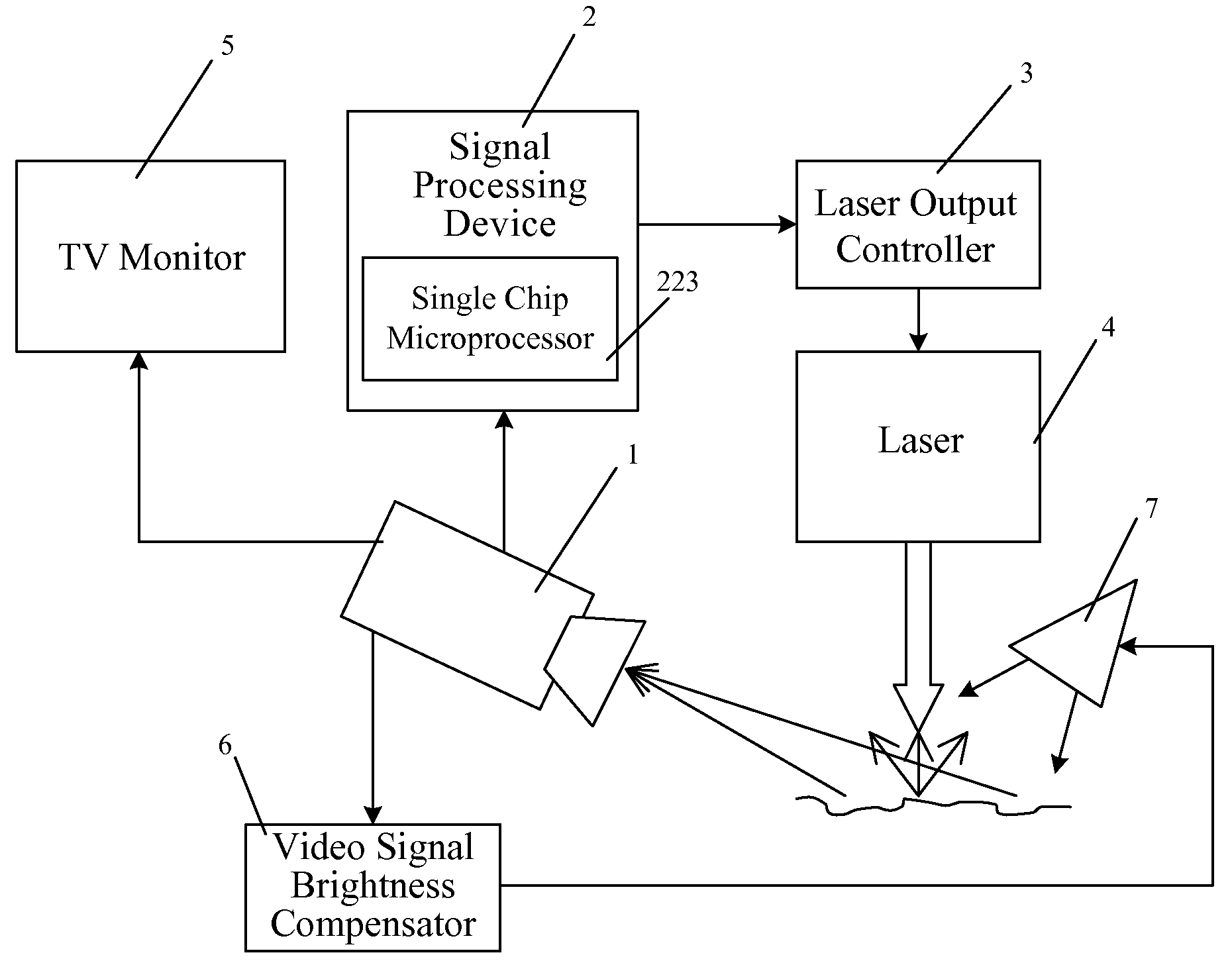
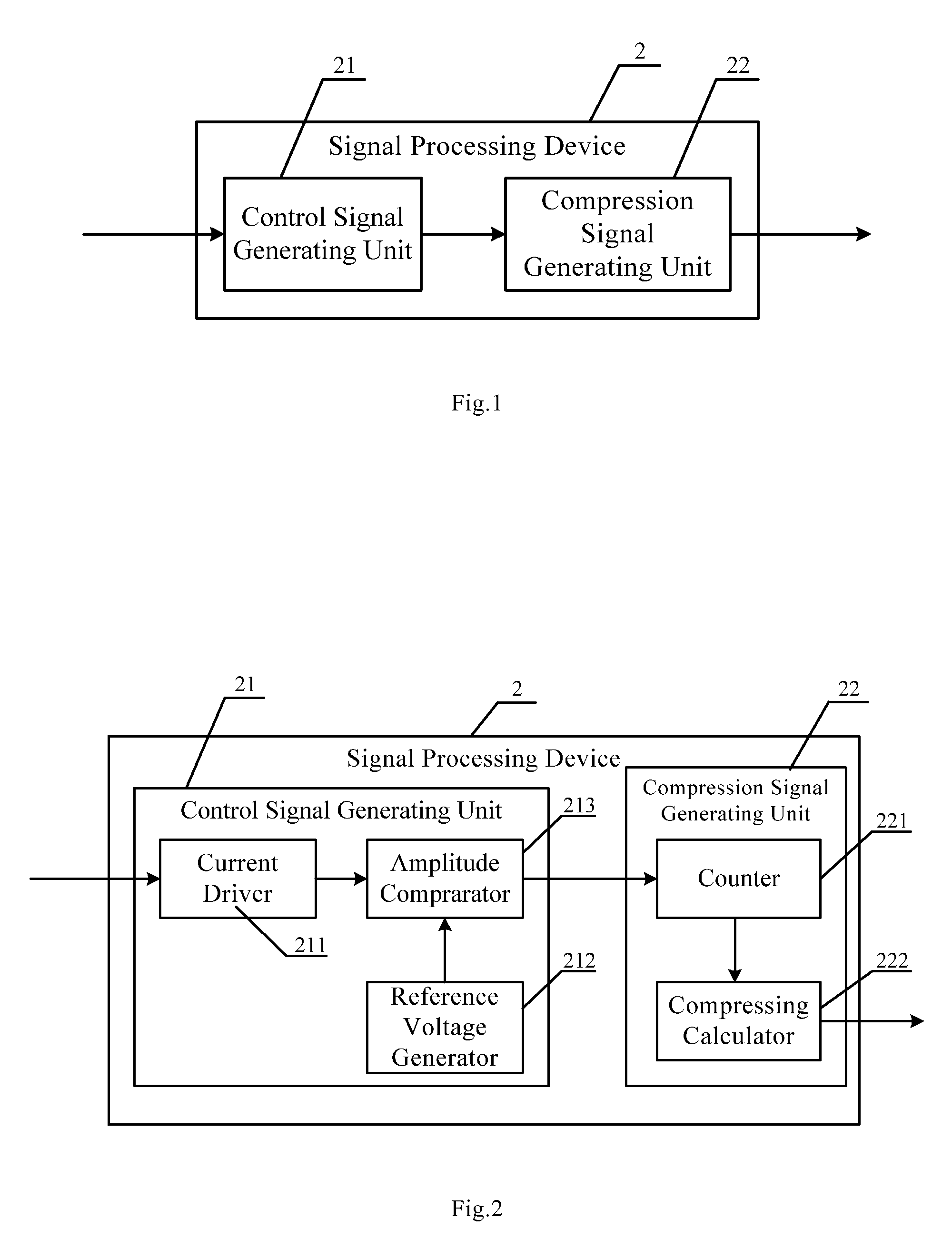
[0026]FIG. 1 is a structure view of a signal processing device for controlling the laser output according to the present invention. The signal processing device 2 includes a control signal generating unit 21 for generating a control signal according to the pulse signal of the electronic shutter by image acquisition and a compression signal generating unit 22 for compressing the pulse width of the generated envelope signal according to the influence time on the image acquisition from the optical noise of the interaction between the laser and the material. Said envelope signal is a signal for controlling the laser output. The input of the control signal generating unit 21 is a pulse signal of the electronic shutter. After being processed, the control signal is outputted. The control signal can be a pulse signal or an envelope signal having the same frequency with the pulse signal of the electronic shutter or other signals having the same frequency with the pulse signal of the electron...
embodiment 2
[0027]FIG. 2 is a structure view of a signal processing device for controlling the laser output according to the present invention. The signal processing device 2 includes a control signal generating unit 21 and a compression signal generating unit 22. The control signal generating unit 21 includes a current driver 211 for performing current amplification on the pulse signal of the electronic shutter, a reference voltage generator 212 for outputting a reference voltage and an amplitude comparator 213 for outputting the control signal after comparing the pulse signal of the electronic shutter after being performed the current amplification with the reference voltage. The input of the amplitude comparator 213 is connected to the current driver 211 and the reference voltage generator 212 and the outputted control signal is a pulse signal. The compression signal generating unit 22 includes a counter 221 for counting the pulse number of the pulse signal and a compressing calculator 222 f...
embodiment 3
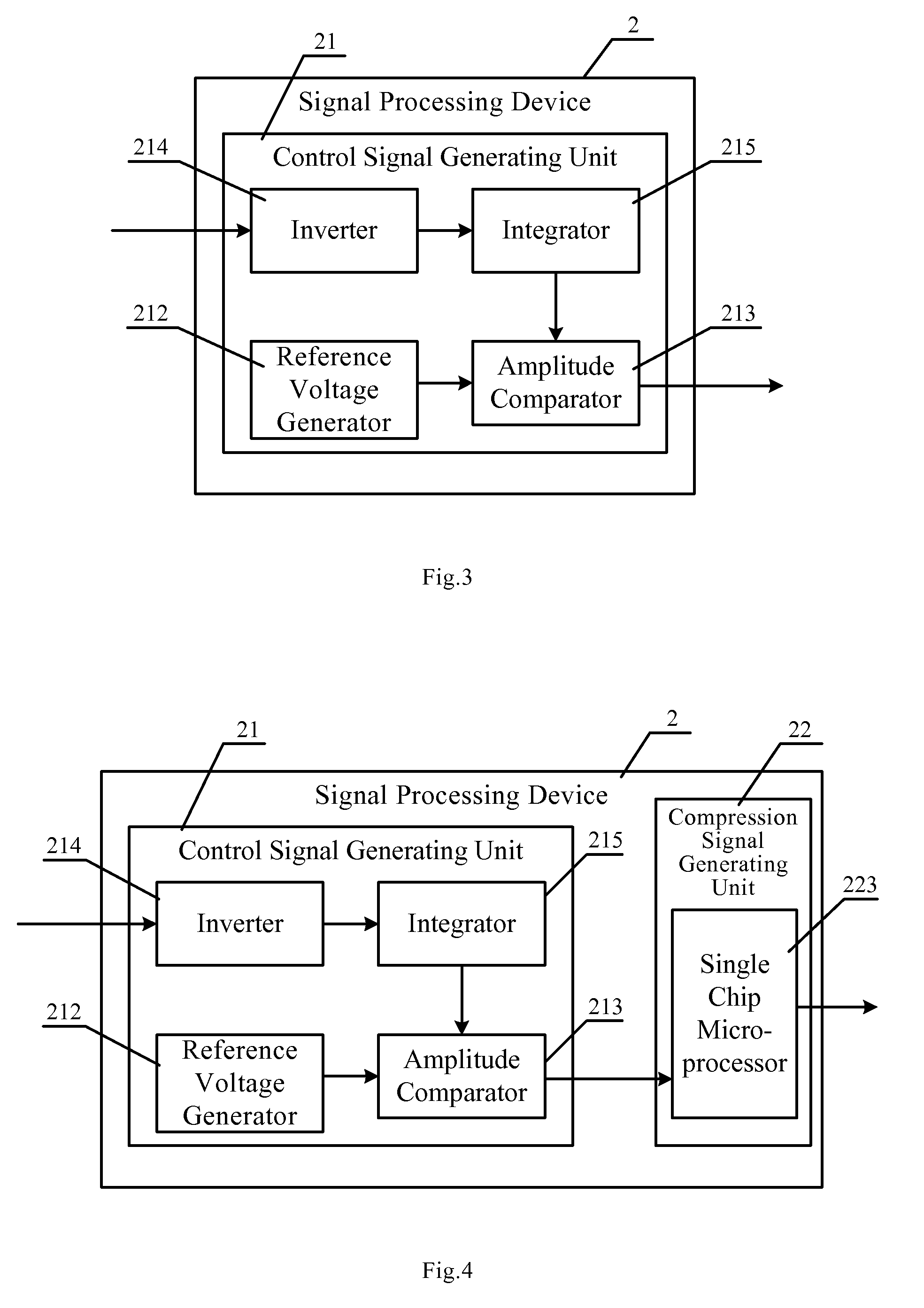
[0030]FIG. 3 is a structure view of a signal processing device for controlling the laser output according to the present invention. The signal processing device 2 includes a control signal generating unit 21 and a compression signal generating unit 22. The control signal generating unit 21 includes an inverter 214 for reversing the phase of the pulse signal of the electronic shutter, an integrator 215 for integrating the signal with reversed phase, the input of which is connected to the inverter 214, a reference voltage generator 212 for outputting a reference voltage and an amplitude comparator 213 for outputting a control signal after comparing the signal outputted form the integrator 215 with the reference voltage. The input of the amplitude comparator 213 is connected to the integrator 215 and the reference voltage generator 212 and the control signal is an envelope pulse signal.
[0031]The phase of the pulse signal of the electronic shutter is reversed by the inverter 214 and the...
PUM
| Property | Measurement | Unit |
|---|---|---|
| Width | aaaaa | aaaaa |
| Phase | aaaaa | aaaaa |
| Brightness | aaaaa | aaaaa |
Abstract
Description
Claims
Application Information
 - R&D
- Intellectual Property
- Life Sciences
- Materials
- Tech Scout
- Unparalleled Data Quality
- Higher Quality Content
- 60% Fewer Hallucinations
Browse by: Latest US Patents, China's latest patents, Technical Efficacy Thesaurus, Application Domain, Technology Topic, Popular Technical Reports.
© 2025 PatSnap. All rights reserved.Legal|Privacy policy|Modern Slavery Act Transparency Statement|Sitemap|About US| Contact US: help@patsnap.com


