Real-Time NMR Distribution While Drilling

Active Publication Date: 2009-11-26
BAKER HUGHES INC
View PDF44 Cites 40 Cited by
  • Summary
  • Abstract
  • Description
  • Claims
  • Application Information

AI Technical Summary

Problems solved by technology

One basic problem encountered in NMR logging or MRI (imaging) is the vast amount of data that has to be analyzed.
In well logging with wireline instruments, the downhole processing capabilities are limited as is the ability to transmit data to an uphole location for further analysis since all the data are typically sent up a wireline cable with limited bandwidth.
In the so-called Measurement-while-drilling methods, the problem is exacerbated due to the harsh environment in which any downhole processor must operate and to the extremely limited telemetry capability: data are typically transmitted at a rate of no more than twenty bits per second.
A second problem encountered in NMR logging and MRI is that of analysis of the data.
Since oil is found in porous rock formations, the relationships between porous rocks and the fluids filling their pore spaces are extremely complicated and difficult to model.
Nuclear magnetic resonance is sensitive to main petrophysical parameters, but has no capabilities to establish these complex relationships.
However, such oil by itself is a very complex mixture of hydrocarbons that may be viewed as a broad spectrum of relaxation times. In a simple case of pure fluid in a single pore, there are two diffusion regimes that govern the relaxation

Method used


Image

  • Real-Time NMR Distribution While Drilling
  • Real-Time NMR Distribution While Drilling
  • Real-Time NMR Distribution While Drilling

Examples


Embodiment Construction

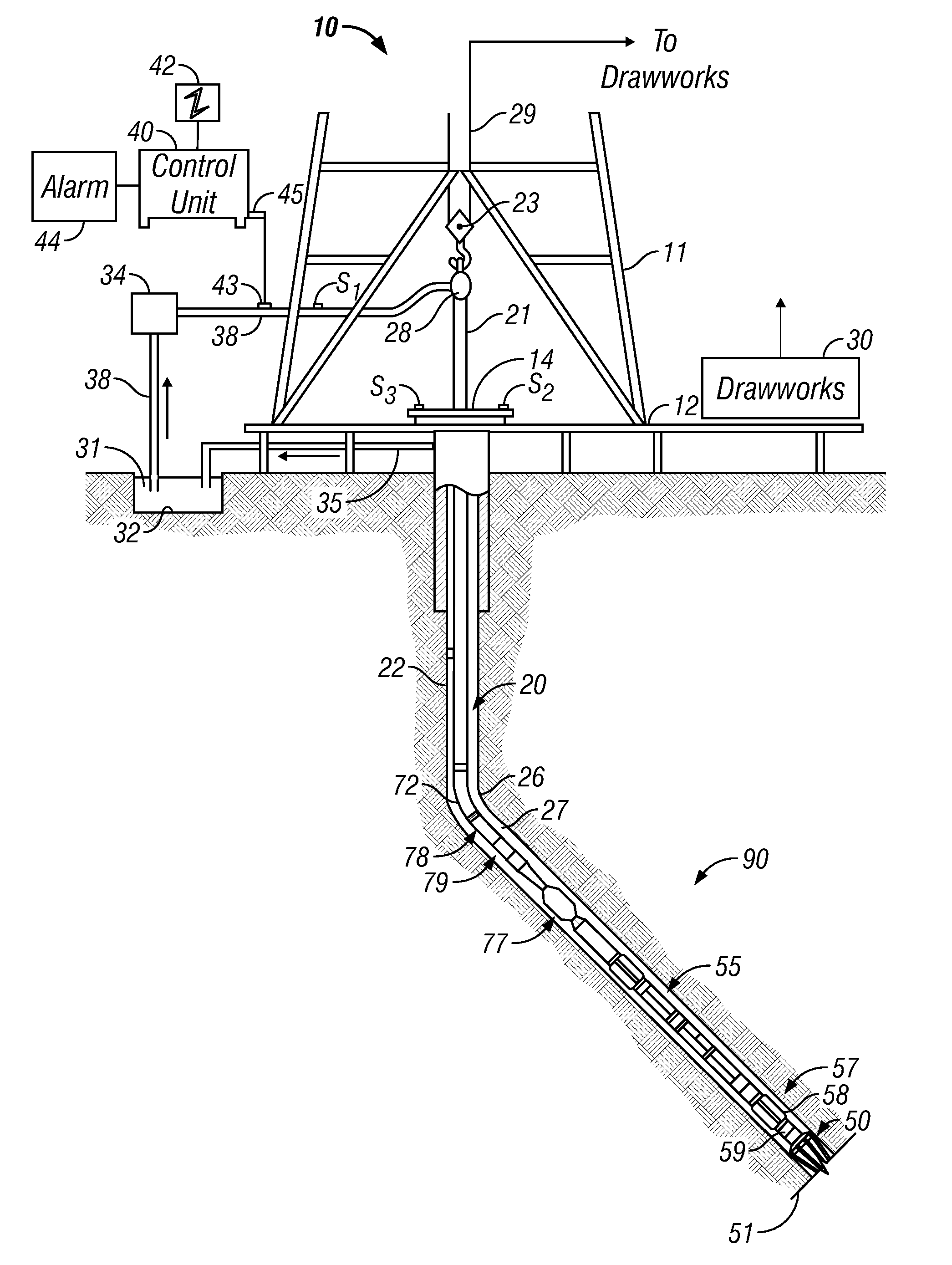
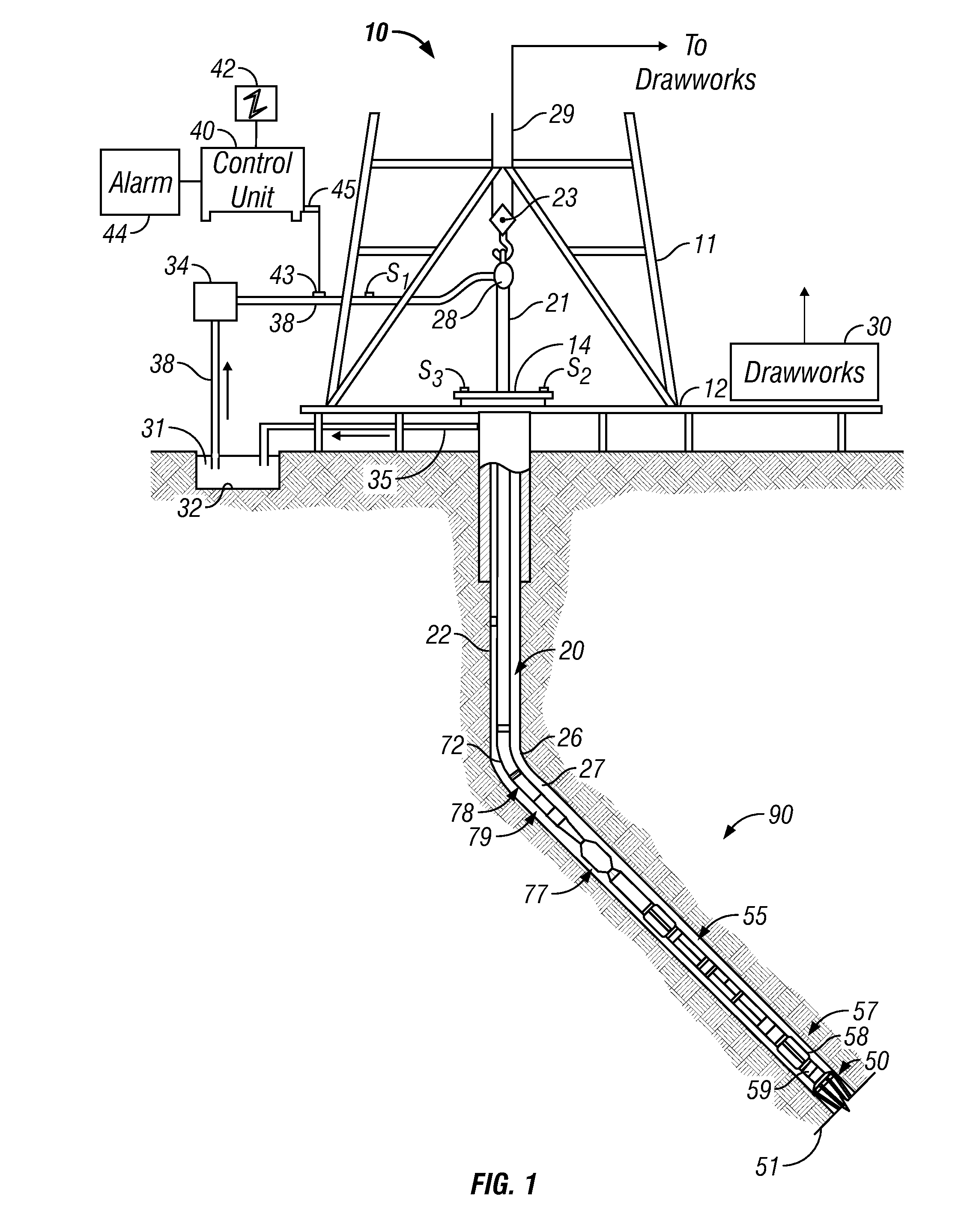
[0037]FIG. 1 shows a schematic diagram of a drilling system 10 with a drillstring 20 carrying a drilling assembly 90 (also referred to as the bottom hole assembly, or “BHA”) conveyed in a “wellbore” or “borehole”26 for drilling the wellbore. The drilling system 10 includes a conventional derrick 11 erected on a floor 12 which supports a rotary table 14 that is rotated by a prime mover such as an electric motor (not shown) at a desired rotational speed. The drillstring 20 includes a tubing such as a drill pipe 22 or a coiled-tubing extending downward from the surface into the borehole 26. The drillstring 20 is pushed into the wellbore 26 when a drill pipe 22 is used as the tubing. For coiled-tubing applications, a tubing injector, such as an injector (not shown), however, is used to move the tubing from a source thereof, such as a reel (not shown), to the wellbore 26. The drill bit 50 attached to the end of the drillstring breaks up the geological formations when it is rotated to dri...


PUM


Abstract

NMR spin echo signals are acquired downhole. Principal Component Analysis is used to represent the signals by a weighted combination of the principal components and these weights are telemetered to the surface. At the surface, the NMR spin echo signals are recovered and inverted to give formation properties. Real-time displays may be used for determining formation properties and for altering the acquisition parameters

Description

CROSS-REFERENCES TO RELATED APPLICATIONS[0001]This applications claims priority from U.S. Provisional Patent Application Ser. No. 61 / 055,803 filed on May 23, 2008.BACKGROUND OF THE DISCLOSURE[0002]1. Field of the Disclosure[0003]The present disclosure relates generally to determining geological properties of subsurface formations using Nuclear Magnetic Resonance (“NMR”) methods for logging wellbores, particularly for representing NMR echo trains by a limited number of functional parameters, enabling efficient transmission of echo train from a downhole location.[0004]2. Description of the Related Art[0005]NMR methods are among the most useful non-destructive techniques of material analysis. When hydrogen nuclei are placed in an applied static magnetic field, a small majority of spins are aligned with the applied field in the lower energy state, since the lower energy state in more stable than the higher energy state. The individual spins precess about the axis of the applied static m...

Claims


Application Information

Patent Timeline
IPC IPC(8): G01V3/08G01V3/18G06F19/00
CPCG01V3/32
Inventor KRUSPE, THOMASTHERN, HOLGER F.ROTTENGATTER, PETERHAMDAN, MOUIN
Owner BAKER HUGHES INC
Why Eureka
Try Eureka