Hybrid-type synchronous machine
a synchronous machine and hybrid technology, applied in the direction of windings, synchronous machines with stationary armatures and rotating magnets, dynamo-electric components, etc., can solve the problems of torque decrease, loss due to d-axis current, and decrease in the amount of magnetic flux of the magnet that crosses the stator coil, so as to reduce the effect of d-axis current loss, increase the field magnetic flux, and reduce the effect of efficiency
- Summary
- Abstract
- Description
- Claims
- Application Information
AI Technical Summary
Benefits of technology
Problems solved by technology
Method used
Image

Examples
first embodiment
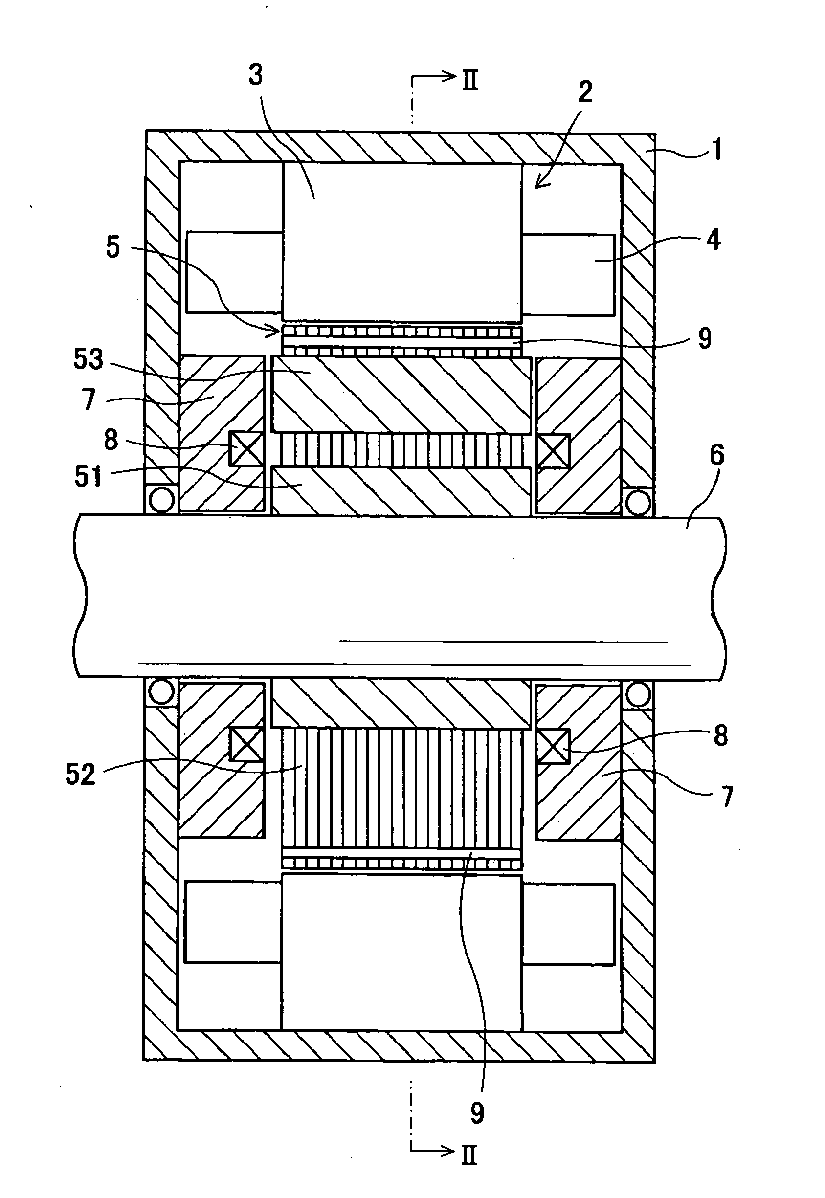
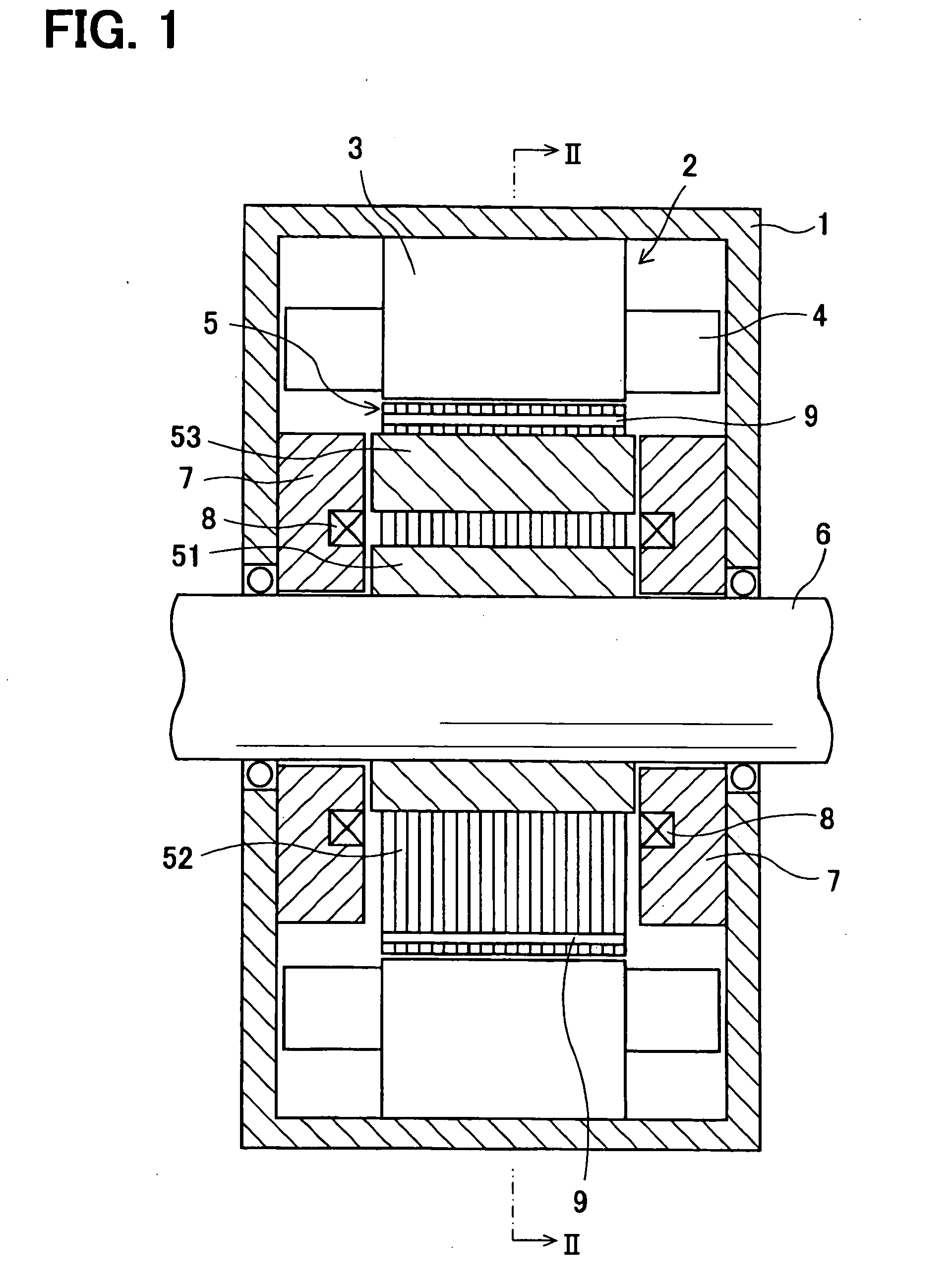
[0021]A hybrid excitation-type synchronous machine according to a first embodiment will be described with reference to FIGS. 1 and 2.
[0022]Referring to FIG. 1, a motor frame 1 supports a stator 2. The stator 2 includes a stator core 3 and a stator coil 4. The stator core 3 is made of a cylindrical soft magnetic member fixed to the inner peripheral surface of the motor frame 1. The stator coil 4 is wound on the stator core 3. A rotor core 5 is press-fitted and fixed to a rotation shaft 6 and accommodated radially inside the stator core 3. A pair of stationary magnetic path members 7, a pair of excitation coils 8 and eight permanent magnets 9 fitted to the rotor core 5 are provided. A small gap is provided between the outer peripheral surface of the rotor core 5 and the inner peripheral surface of the stator core 3.
[0023]The pair of the stationary magnetic path members 7 is separately fixed to end surfaces of the motor frame 1 and face the rotor core 5 with small gaps relative to the ...
second embodiment
[0034]The hybrid excitation-type synchronous machine according to a second embodiment is different from the first embodiment in that, as shown in FIG. 4, the stationary magnetic path member 7, the inner cylindrical part 51 and the axial magnetic path member 53 have different shapes. Specifically, the inner cylindrical part 51 and the axial magnetic path member 53 protrude more in the axial direction than in the first embodiment and face the peripheral surface of the cylindrical stationary magnetic path member 7 with small gaps in the radial direction. Thus, magnetic attraction force between the inner cylindrical part 51, the axial magnetic path member 53 and the stationary magnetic path member 7 works in the radial direction. As a result, the axial thrust working on the rotor core 5 can be reduced.
third embodiment
[0035]The hybrid excitation-type synchronous machine according to a third embodiment is different from the first embodiment in that, as shown in FIG. 5, the stationary magnetic path member 7 has different shape. Specifically, the stationary magnetic path member 7, which is soft magnetic, is formed of spirally-wound steel plate parts 72 and 73. However, the entire shape of the stationary magnetic path member 7 according to the third embodiment is generally the same as that of the stationary magnetic path member 7 according to the first embodiment. The spirally-wound steel plate part 72 is located outside the excitation coil 8 in the radial direction and formed by spirally winding a thin electromagnetic belt steel plate. The spirally-wound plate part 73 is located inside the excitation coil 8 in the radial direction and formed by spirally winding a thin electromagnetic belt steel plate. According to this configuration, the eddy current in the stationary magnetic path member 7 can be r...
PUM
 Abstract
Description
Claims
Application Information
 - R&D
- Intellectual Property
- Life Sciences
- Materials
- Tech Scout
- Unparalleled Data Quality
- Higher Quality Content
- 60% Fewer Hallucinations
Browse by: Latest US Patents, China's latest patents, Technical Efficacy Thesaurus, Application Domain, Technology Topic, Popular Technical Reports.
© 2025 PatSnap. All rights reserved.Legal|Privacy policy|Modern Slavery Act Transparency Statement|Sitemap|About US| Contact US: help@patsnap.com