Zoom camera arrangement comprising multiple sub-cameras

a camera and sub-camera technology, applied in the field of optical and electronic devices, can solve the problems of increasing the size and price of the camera arrangement, increasing the complexity of the manufacturing process, and increasing the importance of manufacturing costs

Inactive Publication Date: 2009-12-03
VALTION TEKNILLINEN TUTKIMUSKESKUS
View PDF13 Cites 118 Cited by
  • Summary
  • Abstract
  • Description
  • Claims
  • Application Information

AI Technical Summary

Benefits of technology

[0011]one or more digital image sensor chips for converting light into electric signal, each chip comprising a sensor area for capturing light funneled by at least one associated sub-camera entity of said two or more sub-camera entities,wherein each of said sub-camera entities comprises a lens assembly incorporating a number of lenses disposed as one or more lens layers of the lens assembly, said number of lenses of said lens assembly being fixedly positioned relative to the associated digital image sensor chip of said one or more digital image sensor chips, wherein the lens assemblies of said two or more sub-camera entities are selected so as to provide two or more different zoom steps, respectively, for enabling the imaging apparatus to provide a particular zoom step of a multi-level optical zoom functionality via the selection of the corresponding sub-camera entity.
[0012]The above zoom camera arrangement, wherein certain optical zoom step (angle of view), or “zoom level”, is advantageously provided via the selection of the associated sub-camera entity, is, depending on the utilized materials, preferably suitable for reflow manufacturing of an imaging apparatus and it may be implemented as one or more camera modules that may be advantageously coupled via a reflow soldering method to a substrate such as a printed circuit board like many other components. The used materials shall be preferably selected so as to maintain their preferred properties such as form during the application of the selected reflow method. For example, they should still withstand the heat produced by the reflow, even if the material itself is not to be fluidized during it. Further, the dimensions and structure of the arrangement are such that they enable handling it analogously with other components as more complex adjustment and support structures are not required. In addition to reflow soldering, or as an alternative, also one or more lenses may be manufactured utilizing a method applying the reflow properties of the associated material. Embodiments of the present invention may utilize reflowable (soldering of the camera module and / or forming one or more lenses)) configuration of wide angle and tele imaging lens types in the same camera apparatus. For example, same lens positions may be utilized in each sub-camera for facilitating (reflow) mass fabrication, for instance.
[0020]The utility of the present invention arises from a plurality of issues depending on each particular embodiment. As the arrangement may be manufactured as reflow compatible, the overall manufacturing costs may be kept low and number of manufacturing steps minimized. The camera module comprising e.g. sensor chip(s) and at least part of related optics advantageously withstands the reflow soldering heat and may be thus mounted without complex special procedures or numerous additional process steps, for example. As moving parts are not necessary, the camera arrangement is robust. The size of the sub-camera optics and other elements may be optimized for providing minimum size, and the size of the arrangement is reduced also due to the fact that additional sensors / motors / servo-control are not required. For example, the size of fixed focus wide angle and telephoto lenses is smaller than the size of a corresponding variable focal length zoom lens. Also the lens(es) of a sub-camera may be better optimized for each particular zoom step than being possible with a single variable focal length zoom lens implementation.

Problems solved by technology

In contrast to professional equipment, however, the importance of manufacturing costs and resulting product price has grown considerably in making component selection and production decisions covering mass market consumer electronics apparatuses comprising camera functionality.
Digital zooming is thus mere mathematical data manipulation and guesstimation, whereupon the resulting image is inferior also in perceived quality especially when larger zoom levels are applied.
As the lenses and / or other elements are mechanically moved along the optical axis by electrically controlled motors that shall be thus provided with the camera arrangement together with e.g. position sensor(s), both the size and price of the camera arrangement goes up and manufacturing thereof gets more complicated all along.
It is rather obvious that in order to move lenses a precise control means such as servo-controlled motors are required, which makes the arrangement 102 more complex, fragile, expensive and space-consuming.
However, as in many production-wise preferable, both efficient and affordable, known manufacturing methods the lens arrangement and / or other related, possibly complex elements would be exposed to undue heat and thermal stress, which e.g. in conjunction with multi-part motored optical zoom system with various movable parts being sensitive to heat, might ultimately hinder the use of such methods completely, the lens arrangement and other related elements should be then separately provided in dedicated manufacturing steps, which is in many ways less preferable solution.
In addition, contemporary zoom arrangements require considerable amount of room for the various necessary elements, which impedes manufacturing really compact-sized and light electrical gadgets with optical zoom camera functionality.

Method used


Image

  • Zoom camera arrangement comprising multiple sub-cameras
  • Zoom camera arrangement comprising multiple sub-cameras
  • Zoom camera arrangement comprising multiple sub-cameras

Examples


Embodiment Construction

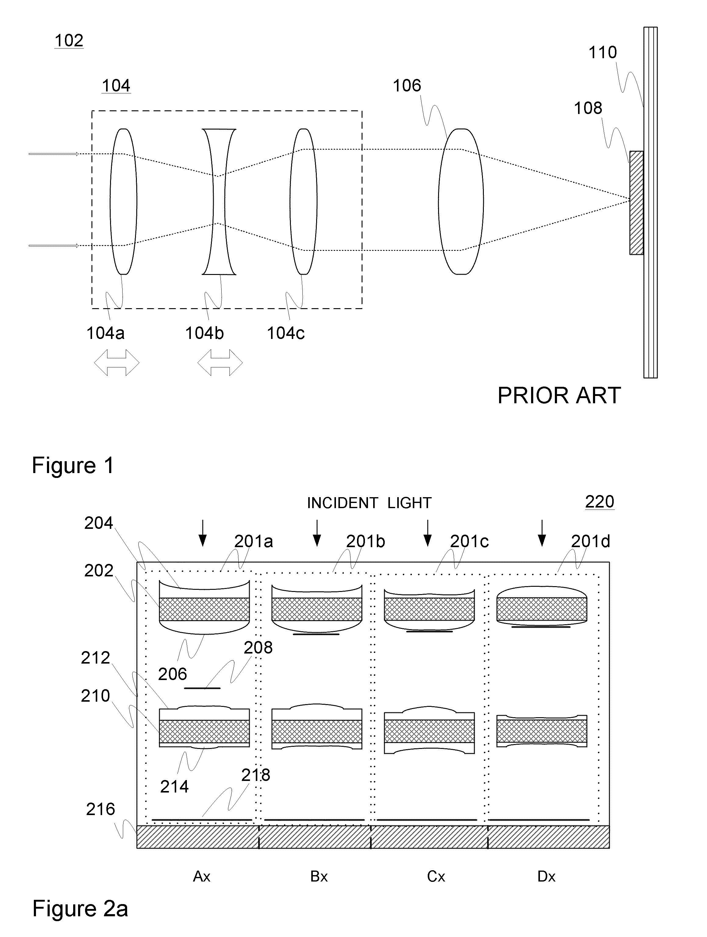
[0030]FIG. 1 was already contemplated hereinbefore in connection with the review of the background of the invention.

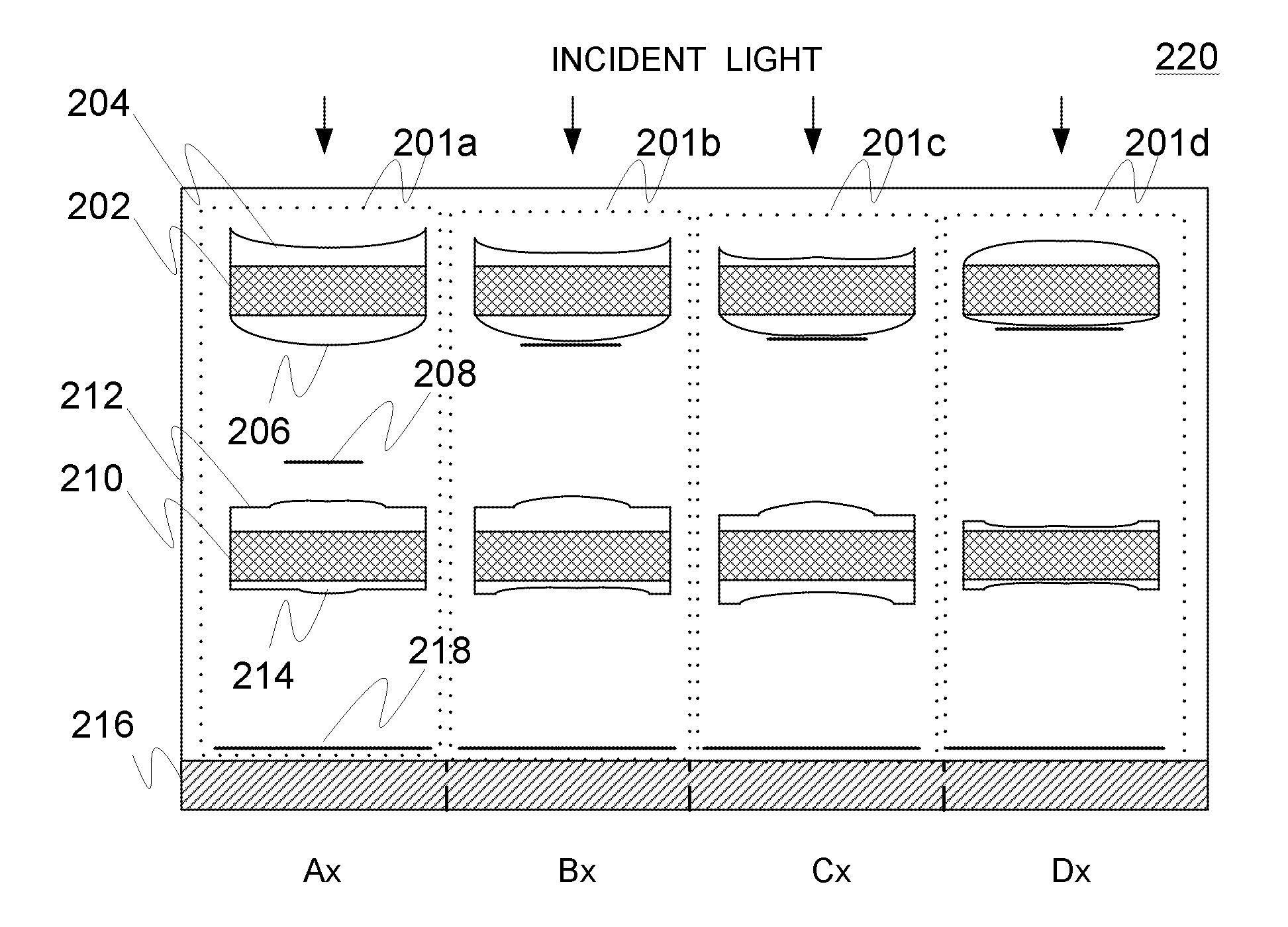
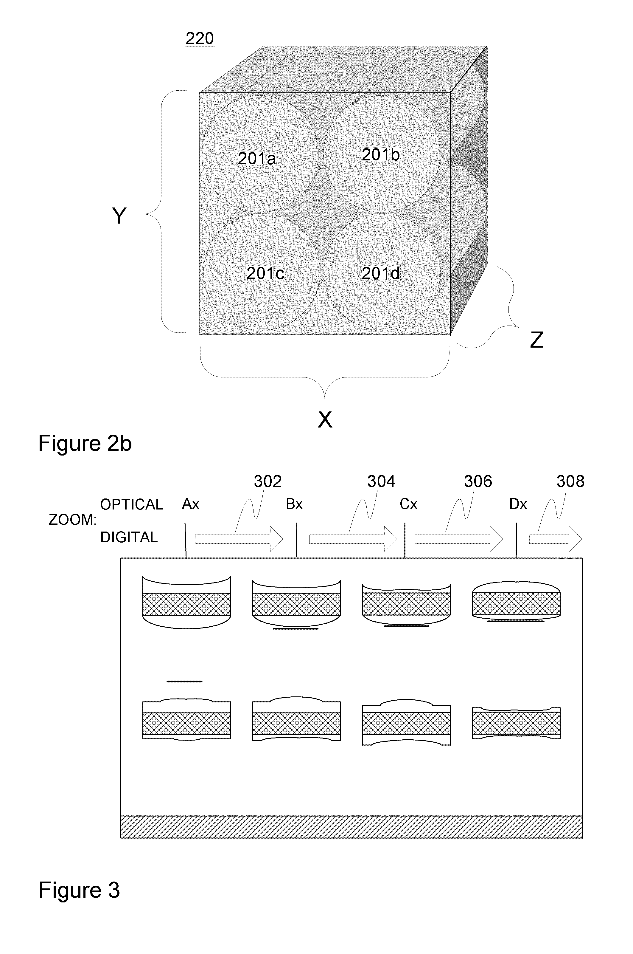
[0031]FIG. 2a illustrates one embodiment 220 of camera arrangement in accordance with the present invention. It shall be first noted that the illustrated elements are not necessarily drawn in scale, unless remarks to assume the contrary are explicitly given. In this particular example the arrangement comprises four sub-camera entities 201a, 201b, 201c, and 201d in order to provide four different zoom steps, or “factors”, Ax, Bx, Cx, and Dx, respectively, but in other embodiments other number, e.g. 2, 3, 5, or more, sub-camera entities may be applied. The sub-camera entities can be functionally considered as “lens tubes” or “barrels” that may be deposited adjacent to each other e.g. in matrix or row form. Advantageously, the placement of sub-cameras may be optimized co-operatively with the sensor area(s) such that the size of surplus, i.e. unused, sensor area(s) is mini...


PUM


Abstract

A zoom camera arrangement includes two or more sub-camera entities for funneling incoming light towards one or more associated digital image sensor chips for converting light into electric signal, each chip including a sensor area for capturing light funneled by at least one associated sub-camera entity of the two or more sub-camera entities, wherein each of the sub-camera entities includes a lens assembly incorporating a number of lenses disposed as one or more lens layers of the lens assembly, the number of lenses of the lens assembly being fixedly positioned relative to the at least one associated digital image sensor chip of the one or more digital image sensor chips, wherein the lens assemblies of the two or more sub-camera entities are selected so as to provide two or more different zoom steps, for enabling the imaging apparatus to provide optical zoom functionality via the selection of the sub-camera entity.

Description

FIELD OF THE INVENTION[0001]Generally the invention relates to optics and electronics. Particularly, however not exclusively, the invention pertains to an arrangement for an imaging apparatus such as a digital camera, wherein the arrangement comprises multiple sub-cameras to provide multiple zoom steps.BACKGROUND[0002]Digital imaging, e.g. acquisition of digital still or video image data representing a target view or target entity via a camera apparatus, is nowadays one of the key drivers of the consumer electronics industry. Digital cameras and other devices incorporating them, such as mobile terminals, personal digital assistants (PDAs), and computers in general, have become standard gear of not just imaging professionals but also ordinary consumers in the world of global communication and multimedia almost irrespective of their profession, social status, sex, age, etc.[0003]In contrast to professional equipment, however, the importance of manufacturing costs and resulting product...

Claims


Application Information

Patent Timeline
Patent Type & Authority Applications(United States)
IPC IPC(8): H04N5/262
CPCG02B3/0018G02B3/0062G02B13/001H04N5/2254G02B15/00G03B19/02G02B13/009G02B7/021G02B7/14G03B19/023H01L27/14625H04N23/16H10K39/32
Inventor OJALA, KAI MARKUS
Owner VALTION TEKNILLINEN TUTKIMUSKESKUS
Why Eureka
Try Eureka