
Light diffuser plate with primer layer, process for producing the same, laminated optical member, surface light source apparatus and liquid crystal display

Inactive Publication Date: 2009-12-03
SUMITOMO CHEM CO LTD
View PDF5 Cites 13 Cited by
  • Summary
  • Abstract
  • Description
  • Claims
  • Application Information

AI Technical Summary

Benefits of technology

[0009]As a result of the present inventor's intensive studies to solve The problem, it is found that a laminated optical member excellent in bonding strength for lamination can be obtained by laminating a primer layer on at least one surface of a light diffuser plate, and integrally laminating an optical film on the primer layer through an adhesive layer.
[0055]In the invention of the item [17], the liquid crystal display is assembled using the laminated optical member comprising the light diffuser plate and the optical film laminated on each other. Therefore, the liquid crystal display is improved in handling efficiency, and thus is excellent in productivity, ensuring a sufficient bonding strength between the light diffuser plate and the optical film, and showing a high quality and a high luminance.

Problems solved by technology

However, despite an increasing demand for large-sized liquid crystal displays in these years, the handling efficiency for assembling such surface light source apparatuses tends to degrade.

Method used


Image

  • Light diffuser plate with primer layer, process for producing the same, laminated optical member, surface light source apparatus and liquid crystal display
  • Light diffuser plate with primer layer, process for producing the same, laminated optical member, surface light source apparatus and liquid crystal display
  • Light diffuser plate with primer layer, process for producing the same, laminated optical member, surface light source apparatus and liquid crystal display

Examples


example 1

Preparation of Light-Diffusing Agent Master Batch

[0151]Styrene resin pellets (“HRM40” manufactured by TOYO STYRENE CO., LTD.; refractive index: 1.59) (54 parts by mass), acrylic polymer particles (crosslinked polymer particles, “SUMIPEX XC1A” manufactured by Sumitomo Chemical Company, Limited; refractive index: 1.49; volume-average particle size: 25 μm (40 parts by mass), siloxane-based polymer particles (crosslinked polymer particles, “Trefil DY33-719” manufactured by Dow Corning Toray; refractive index: 1.42; volume-average particle size: 2 μm (4 parts by mass), a thermal stabilizer (“Sumisorb 200” in the form of powder, manufactured by Sumitomo Chemical Company, Limited) (2 parts by mass) and a processing stabilizer (“Sumilizer GP” in the form of powder, manufactured by Sumitomo Chemical Company, Limited) (2 parts by mass) were dry-blended. Then, this blend was charged in the hopper of a twin-screw extruder and was melt-kneaded while being heated. After that, this knead mixture w...

example 2

[0156]A light diffuser plate was obtained in the same manner as in Example 1, except that there was used a primer solution comprising a mixture of “NeoRez® R-600” (100 parts by mass) manufactured by DSM Neoresins and “CARBODILITE® V02-L2” (7.5 parts by mass) manufactured by NISSHINBO INDUSTRIES, INC.

example 3

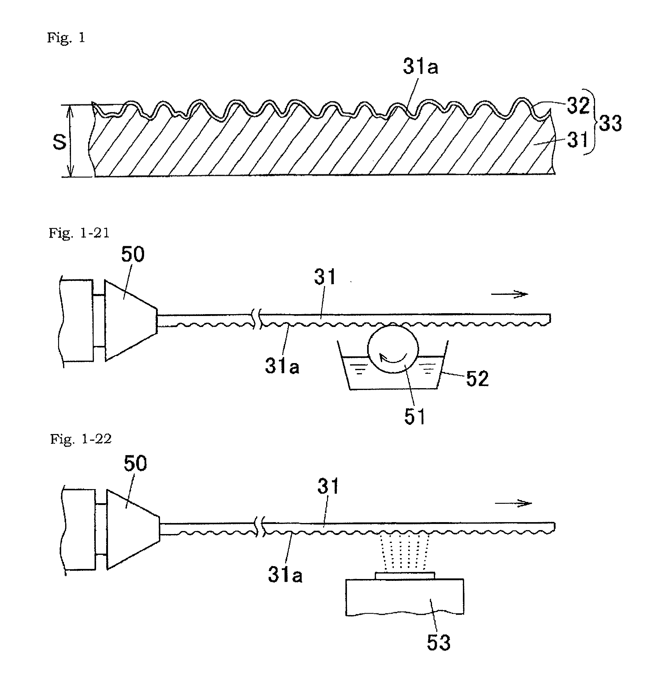
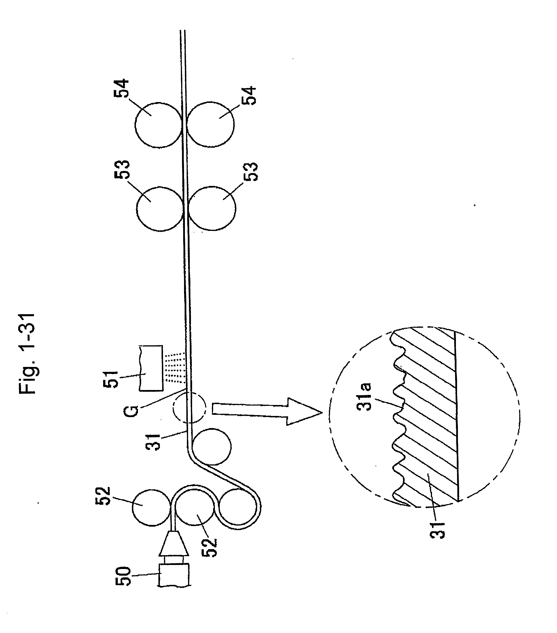
[0157]There was produced a synthetic resin-made light diffuser plate (31) with a thickness of 2 mm which had an uneven surface (31a) formed on one surface thereof by forming a plurality of cylindrical lens-shaped protrusions on the entire surface by melt extrusion and transfer molding with the use of an engraved roller (see FIG. 6). In this light diffuser plate (31), the height (H) of each of the substantially semi-circular sections of the cylindrical protrusions was about 100 μm; each of the pitch intervals (P) between each of the adjacent protrusions having the substantially semi-circular sections was about 230 μm; and each of the widths (E) of the flat-bottomed grooves between each of the adjacent protrusions was about 15 μm.

[0158]A primer solution comprising a mixture of “NeoRez® R-551” (100 parts by mass) manufactured by DSM Neoresins and “CARBODILITE® V02-L2” (8.3 parts by mass) manufactured by NISSHINBO INDUSTRIES, INC. was applied to the uneven surface (31a) of the light dif...


PUM

PropertyMeasurementUnit
Temperatureaaaaaaaaaa
Lengthaaaaaaaaaa
Linear densityaaaaaaaaaa

Abstract

The present invention relates to a light-diffuser-plate-with-primer-layer, which permits lamination of an optical film or the like thereon with a sufficient bonding strength, and a process for producing the same efficiently and at a lower cost.

Description

TECHNICAL FIELD[0001]The present application is filed, claiming the Paris Convention priorities of Japanese Patent Application Nos. 2008-069858 (filed on Mar. 18, 2008), 2008-082528 (filed on Mar. 27, 2008) and 2008-082533 (filed on Mar. 27, 2008), the entire contents of which are incorporated herein by reference.[0002]The present invention relates to a light-diffuser-plate-with-primer-layer, which permits lamination of an optical film or the like thereon with a sufficient bonding strength, and a process for producing the same light diffuser plate at a higher efficiency and at a lower cost.BACKGROUND ART[0003]For example, a typically known liquid crystal display comprises a liquid crystal panel (an image-displaying member) including a liquid crystal cell, and a surface light source apparatus as a backlight disposed on the back side of the liquid crystal panel. As this surface light source apparatus for use as a backlight, there is known a surface light source apparatus comprising a ...

Claims


Application Information

Patent Timeline
IPC IPC(8): G02F1/13357G02B5/02B32B37/12
CPCB32B27/30G02B5/0221G02B5/0231Y10T156/10G02B5/0278G02F2001/133607G02B5/0268B32B7/12B32B23/08B32B27/08B32B27/281B32B27/283B32B27/285B32B27/286B32B27/302B32B27/304B32B27/306B32B27/308B32B27/32B32B27/34B32B27/36B32B27/365B32B3/30B32B2255/00B32B2307/412B32B2307/42B32B2307/518B32B2457/206G02F1/133607
Inventor KANAYA, HIROKOKANEMITSU, AKIYOSHIMORI, MASAHARU
Owner SUMITOMO CHEM CO LTD
Learn More