
Illumination device for use in endoscope

a technology of endoscope and illumination device, which is applied in the field of endoscope illumination device, can solve the problems of difficult to secure the thickness of the light guide, noise is easily superimposed on the captured image, and the light guide serving as an optical path becomes bulky, etc., and achieves the effect of low cost and small and thin

Active Publication Date: 2009-12-10
FUJIFILM CORP
View PDF39 Cites 205 Cited by
  • Summary
  • Abstract
  • Description
  • Claims
  • Application Information

AI Technical Summary

Benefits of technology

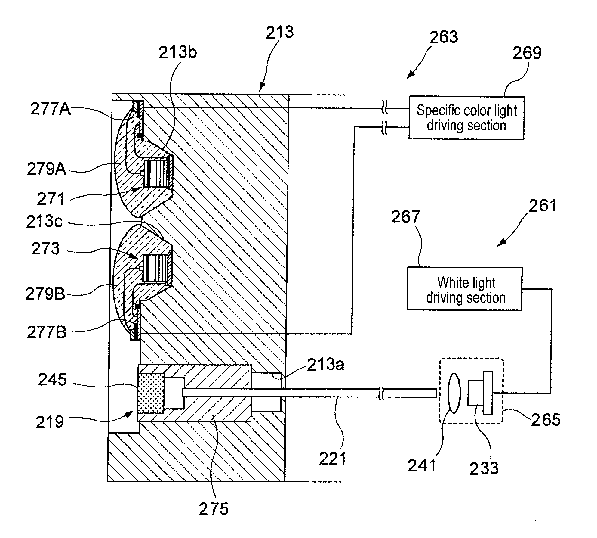
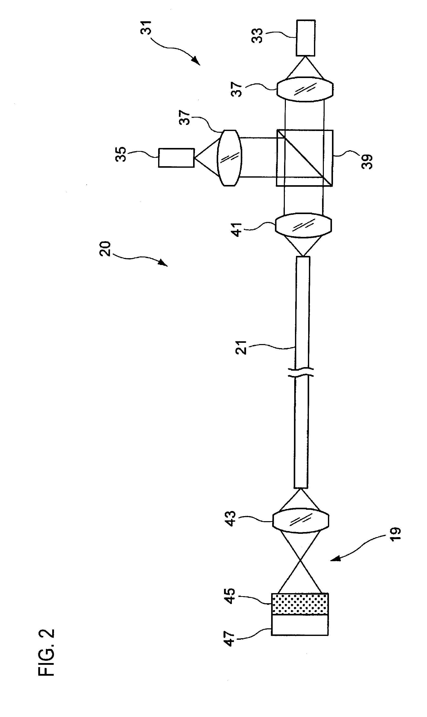
[0035]With this light source device, since the second wavelength conversion member is disposed anterior to the first wavelength conversion member on the optical path, the luminescence from the first wavelength conversion member is transmitted through the second wavelength conversion member while diffusing through the second wavelength conversion member. As a result, the white light is emitted while being diffused. Moreover, the laser beam of the second light source is transmitted through the second wavelength conversion member without loss while exciting the second wavelength conversion member to emit the luminescence in the specific wavelength band. The white light and the luminescence are emitted frontward on the optical path.(3) In the light source device of (1), the second wavelength conversion member may be formed to be included in a light guiding material of the optical fiber.
[0079]According to the above-described configuration of any one of (34) to (45), it is possible to provide a light source device that can be made small and thin by making two emitted light components having different wavelengths guided coaxially and that can be made at low cost and has many applications, and an endoscope apparatus using the light source device. Furthermore, according to the above-described configuration of any one of (34) to (45), efficient white illumination and miniaturization of the device can be realized, and it is possible to make emission sources of white light and infrared light almost the same or the white light and the infrared light can be guided coaxially so that the emission positions thereof can be made almost the same. For example, comparison between both images can be easily performed by decreasing a difference between the images or appearance of shadows even when the normal image under the white light and the image under the infrared light are acquired in a time-series manner and displayed.

Problems solved by technology

In the case of the nasal endoscope, an insertion portion is thinner than that of the peroral endoscope, and it is difficult to secure the thickness of a light guide.
Moreover, in case of performing illumination with such a green laser, a noise is easily superimposed on a captured image because of speckle (interference) or flickering easily occurs on a dynamic image due to the high coherence.
However, particularly in an endoscope, a light guide serving as an optical path becomes bulky.
In addition, since it is necessary to provide a new irradiation window at the tip of an insertion portion, it becomes difficult to make the insertion portion thin.
Therefore, in order to acquire a narrow-band imaging signal of a blue or green color which is useful especially for an endoscope, there still remains many problems in a combination of suitable phosphors, switching of excitation light sources in a time-series manner, a signal calculating method, and the like.
That is, it is still difficult to precisely separate the emission wavelength band by switching of excitation light and to make light selectively emitted.
For this reason, since there was limitation in the size of a phosphor when a light emitting device is mounted at the tip portion of the endoscope, there was also limitation in improving the efficiency.
However, the endoscope apparatus described in JP 2641653 B2 is an apparatus in which both light in a visible range and infrared light or ultraviolet light other than the visible range are used by switching light having a narrow-band wavelength in a time-series manner, and such light components are directly incident on a light guide to be then directly irradiated to a body to be inspected from the tip of the light guide, but is not an apparatus that irradiates white light including plural wavelength components in a visible range.
In this case, the infrared light could not be efficiently guided in the related art because the optical fiber which guides the excitation light is configured to efficiently guide the excitation light.
In addition, in the case of a phosphor for use in the known white LED or white laser, there was a problem that the infrared light was wavelength-converted into fluorescent light.
However, the resultant device configuration is complicated, and it is difficult to reduce a size of the device.
Therefore, it is difficult to compare the images.
Therefore, it would be difficult to achieve efficient white illumination and to reduce a size of the device.
Therefore, it is difficult to compare both the images.

Method used


Image

  • Illumination device for use in endoscope
  • Illumination device for use in endoscope
  • Illumination device for use in endoscope

Examples


first embodiment

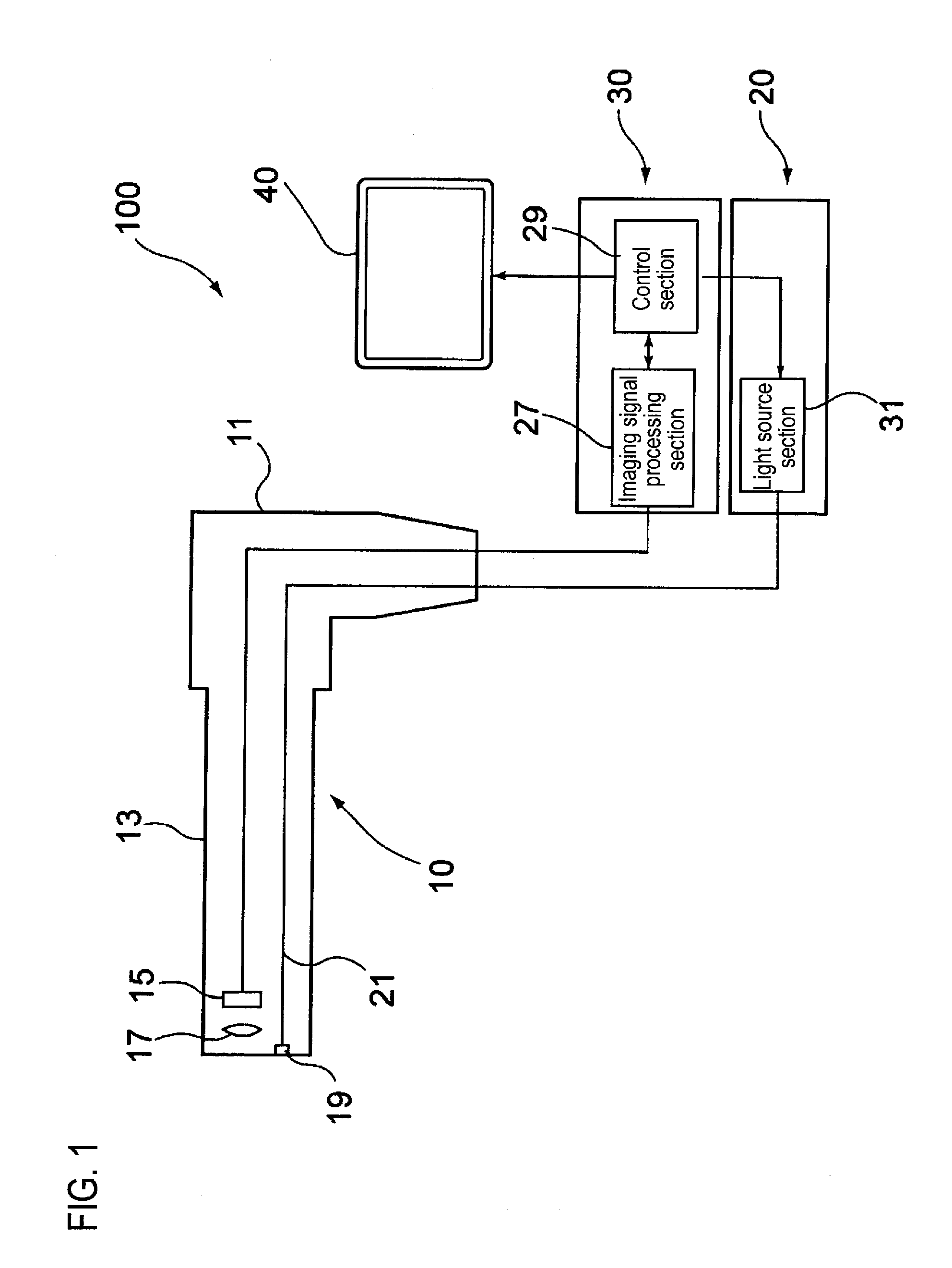
[0118]Hereinafter, a light source device according to a first embodiment and an endoscope apparatus using the light source device will be described in detail with reference to the accompanying drawings. FIG. 1 is a view illustrating the conceptual configuration of the endoscope apparatus according to the first embodiment. An endoscope apparatus 100 of the first embodiment is configured to mainly include an endoscope 10, a light source device 20, an image processing device 30, and a monitor 40. The endoscope 10 includes a main body operation portion 11 and an insertion portion 13 which is provided to be connected to the main body operation portion 11 and is inserted into a body to be inspected (body cavity). A solid-state imaging device 15 and an imaging lens 17 which constitute an imaging optical system are disposed in a tip portion of the insertion portion 13. Moreover, an illumination optical member 19, which is an illumination optical system, and an optical fiber 21 connected to ...

second embodiment

[0135]Next, a second embodiment in which the second wavelength conversion member 47 of the light source device 20 is provided within an optical fiber will be described. FIG. 5 is a configuration view of an optical system illustrating another example of a light source device used in the endoscope apparatus of FIG. 1. Here, description on members which are the same as those in FIG. 2 will be omitted or simplified with the same reference numerals being assigned thereto. The configuration of a light source device 50 is the same as the above-described configuration except that a material of the second wavelength conversion member 47 is contained in a light guiding material of the entire optical fiber 53 or a part of the optical fiber 53 instead of providing a block of the second wavelength conversion member 47 on the light emission side of the optical fiber 53.

[0136]FIG. 6 shows a section view of the optical fiber 53 shown in FIG. 5. The optical fiber 53 is configured to include a core 5...

third embodiment

[0145]Hereinafter, a light source device according to a third embodiment, an endoscope apparatus using this light source device, and an image processing method will be described in detail with reference to the accompanying drawings. FIG. 7 is a view illustrating the conceptual configuration of the endoscope apparatus according to the third embodiment. An endoscope apparatus 101 is configured to mainly include an endoscope 110, a light source device 120, an image processing device 130, and a monitor 140. The endoscope 110 includes a main body operation portion 111 and an insertion portion 113 which is provided to be connected to the main body operation portion 111 and is inserted into a body to be inspected (body cavity). A solid-state imaging device 115 and an imaging lens 117 which constitute an imaging optical system are disposed in a tip portion of the insertion portion 113. Moreover, an illumination optical member 119, which constitutes an illumination optical system, and an opt...


PUM


Abstract

An illumination device for use in an endoscope includes a light source, an optical fiber and a wavelength conversion member. The optical fiber guides light to a tip end of an endoscope insertion portion of the endoscope. The wavelength conversion member is provided at an emission end of the optical fiber. The wavelength conversion member configured to be excited by the light source. The illumination device can provide white illumination light obtained by mixing light emitted from the optical fiber and light obtained by exciting the wavelength conversion member by the light emitted from the optical fiber. Also, the illumination device can provide illumination light being different from the white illumination light, by using other excitation light.

Description

CROSS-REFERENCE TO RELATED APPLICATIONS[0001]This application claims the benefit of Japanese Patent Application Nos. 2008-146660 (filed on Jun. 4, 2008), 2008-152932 (filed on Jun. 11, 2008), 2008-155597 (filed on Jun. 13, 2008) and 2008-156047 (filed on Jun. 13, 2008), the entire contents of which are hereby incorporated by reference, the same as if set forth at length.BACKGROUND OF THE INVENTION[0002]1. Technical Field[0003]The invention relates to an illumination device for use in an endoscope.[0004]2. Description of the Related Art[0005]In light source devices using a laser beam, various types of light source devices which obtain white light by a laser beam and visible light generated by a wavelength conversion member, such as a phosphor excited by the laser beam, have been proposed. In these types of light source devices, a laser beam has a line spectrum in a specific wavelength region. Accordingly, a wavelength region where the emission intensity is low may be generated over a...

Claims


Application Information

Patent Timeline
IPC IPC(8): A61B1/07A61B1/06
CPCA61B1/0638A61B1/0653A61B1/07A61B1/043A61B1/063A61B1/0017A61B1/0684H01S5/4087H01L25/0753H01L2224/48091H01L2224/48465H01L2224/49107H01L2224/73265H01L2924/19107H01L2224/45144H01S5/0087H01S5/02251H01S5/32341H01S5/4012A61B1/0655H01L2924/00014H01L2924/00
Inventor MIZUYOSHI, AKIRA
Owner FUJIFILM CORP
Learn More