High Wear-Resistant Bearing Material and Artificial Joint Replacement Using the Same

a bearing material and high wear resistance technology, applied in the direction of femoral head, shoulder joint, prosthesis, etc., can solve the problems of inability to completely prevent the wear of the bearing surface, the potential of osteolysis, and the burden on the patient, so as to achieve excellent durability, maintain high wear resistance over a long period of time, and avoid osteolysis

Active Publication Date: 2009-12-10
KYOCERA CORP +1
View PDF24 Cites 25 Cited by
  • Summary
  • Abstract
  • Description
  • Claims
  • Application Information

AI Technical Summary

Benefits of technology

[0013]With the background described above, an object of the present invention is to provide a bearing material that is excellent in durability and is capable of maintaining high wear-resistance over a long period of time, and a method for manufacturing the same.
[0014]The present inventors has completed a bearing material for artificial joint of the present invention based on a finding that, in case a polymer layer having a phosphorylcholine group is grafted from a UHMWPE surface, high wear-resistance of the layer depends on the thickness of the polymer layer and there is an optimum range of the thickness.
[0016]The bearing material of the present invention can suppress the wear to a low level even when used under harsh frictional conditions over a long period of time, and therefore reduces the possibility of causing osteolysis that is induced by wear debris. Also because the joint replacement is unlikely to undergo a change in the shape of the bearing surface over an extended period of time, performance of the artificial joint as designed can be maintained. As a result, once joint arthroplasty is conducted, since the artificial joint maintains stable function over a long period of time, the number of replacement surgeries required for the artificial joint can be reduced or the need thereof can be eliminated altogether.
[0019]According to the present invention, a uniform polymer layer having a favorable thickness can be formed by controlling the monomer concentration in feed.
[0020]According to the present invention, there can be provided a bearing material: excellent in durability and is capable of maintaining high wear-resistance over a long period of time.

Problems solved by technology

However, wear debris of UHMWPE generated by frictional motion of the artificial joint used in the human body has a potential of inducing osteolysis.
Then the artificial joint needs to be replaced, thus placing a great burden on the patient.
Even when the bearing surface of a joint replacement is modified to make it resistant to wear, the technologies currently available are not capable of completely prevent wear of the bearing surface.
Thus the bearing material of a joint replacement with the surface modified by the prior art technology may demonstrate high wear resistance in the initial stage of use, but would show rapidly deteriorating wear resistance once the modified surface region has been removed by wear or delamination over a long period of use.
Then, if the decreasing wear resistance leads to the generation of wear debris, the possibility is high for loosening to take place.
The bearing material of a joint replacement made by using the CLPE has a short history of clinical application, and therefore it has not been verified whether its wear resistance would be maintained over an extended period of time.
In case the technique of fixing a film of a random copolymer onto the material surface used for a medical purpose is applied to a bearing material of a joint replacement, the film made of a random copolymer is subjected to severe friction that causes wear and is quite likely to remove the UHMWPE surface.
Thus it is difficult to apply this technology into practical use.
However, it has not been verified whether the wear resistance of this bearing material of a joint replacement would be maintained over an extended period of time.

Method used


Image

  • High Wear-Resistant Bearing Material and Artificial Joint Replacement Using the Same
  • High Wear-Resistant Bearing Material and Artificial Joint Replacement Using the Same
  • High Wear-Resistant Bearing Material and Artificial Joint Replacement Using the Same

Examples


first embodiment

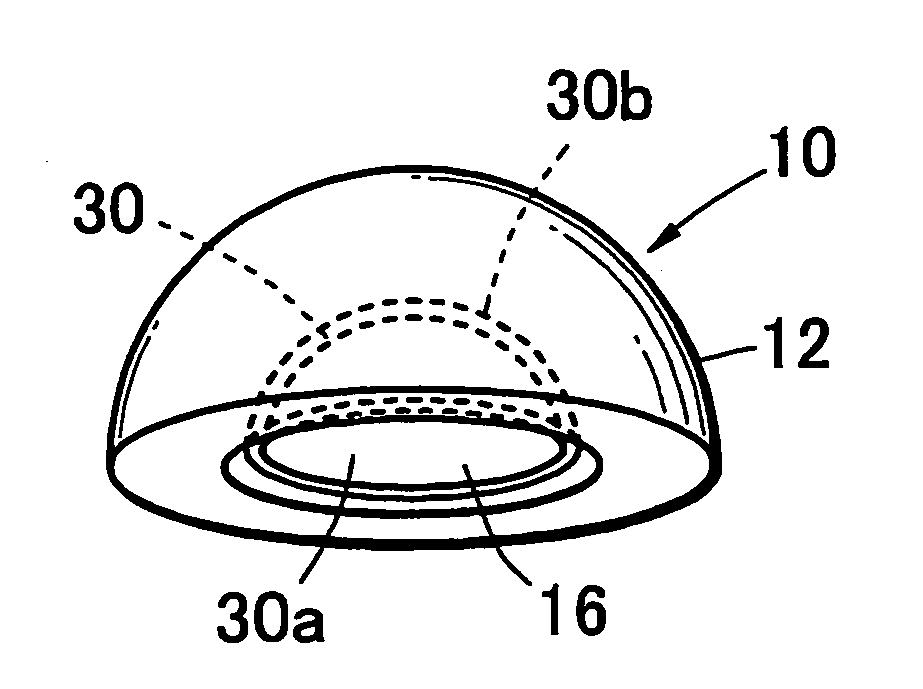
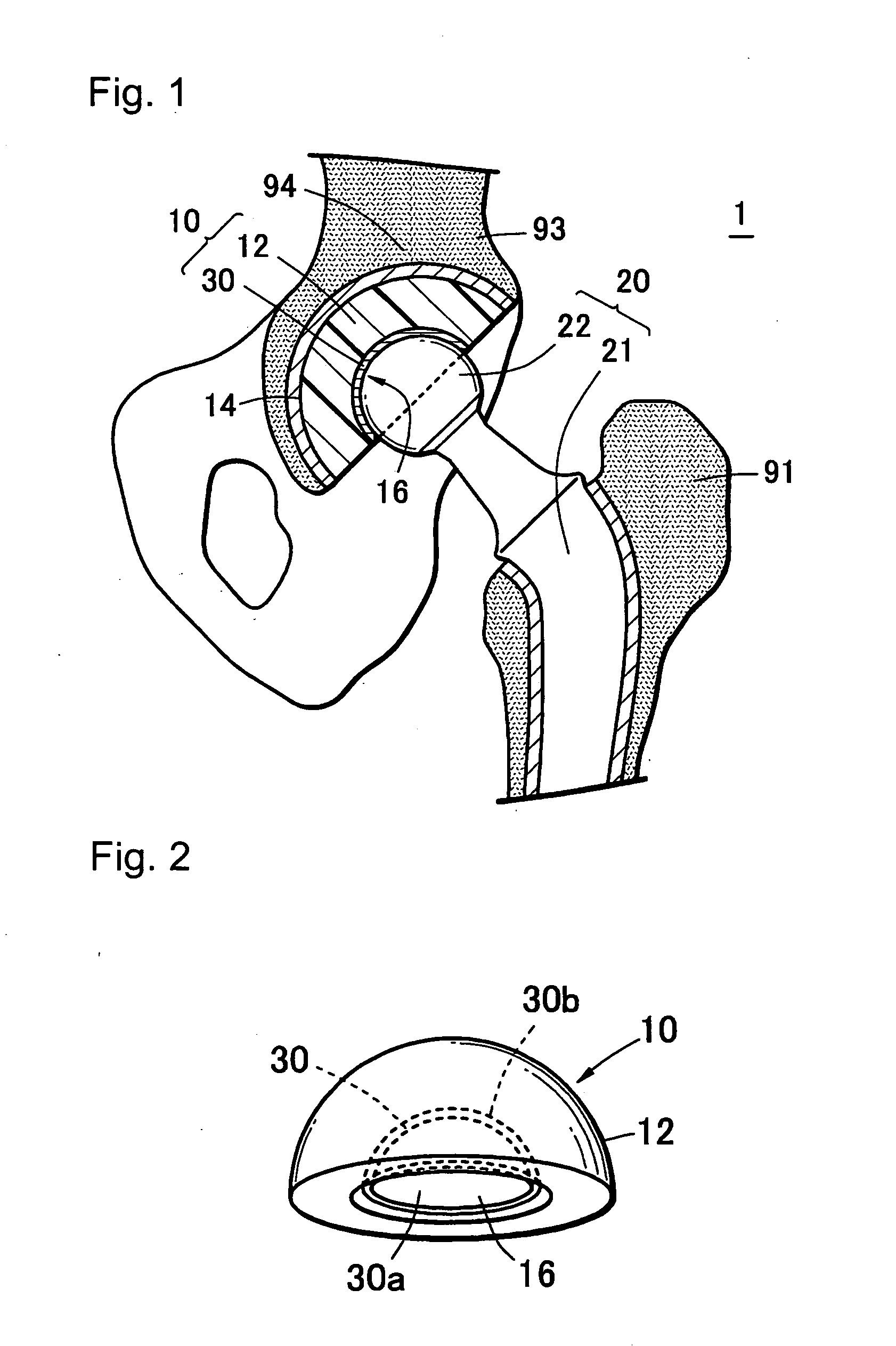
[0073]FIG. 1 is a schematic diagram of an example of artificial joint, an artificial hip joint 1. The artificial hip joint 1 is constituted from a bearing component (acetabular cup) 10 that is fixed onto acetabulum 94 of a hip bone 93 and a femoral stem 20 that is fixed onto a proximal end of a femur 91. The acetabular cup 10 comprises a cup substrate 12 that has a substantially semi-spherical acetabulum fixing surface 14 and a bearing surface 16 of concave semi-spherical shape, and a polymer layer 30 with which the sliding surface 16 is covered. A bone head 22 of a femoral stem 20 is slidably fitted to the bearing surface 16 of the acetabular cup 10, so as to function as a hip joint.

[0074]As shown in FIG. 1 and FIG. 2, the acetabular cup 10 of the present invention is constituted by graft-coating the bearing surface 16 of the cup substrate 12 with a polymer layer 30 having a phosphorylcholine group. The polymer layer 30 has such a molecular structure as polymer chains having a phos...

second embodiment

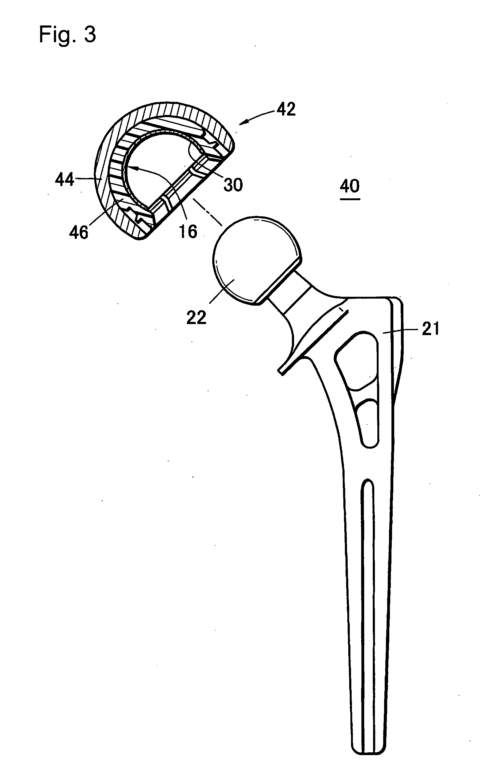
[0100]FIG. 3 shows another artificial hip joint, a bipolar artificial hip joint 40. This artificial hip joint 40 is characterized by the constitution of the femoral head portion that comprises two components of a ball-shaped femoral head 22 and an outer head 42 that accommodates the femoral head 22.

[0101]The femoral head 22 consists of a ball-shaped component made of ceramics or a metal, and is fixed onto a stem body 21 at a proximate portion thereof.

[0102]The outer head 42 is constituted from an outer shell 44 that is a semi-spherical hollow component made of a metal or ceramics, a liner substrate 46 made of UHMWPE fixed onto the inside of the outer shell 44, and the polymer layer 30 fixed onto the spherical sliding surface 16 that is formed in the liner substrate 46. The liner substrate 46 and the polymer layer 30 constitute the bearing materials of the artificial joint. The polymer layer 30 is made of polymer chains having a phosphorylcholine group grafted on the sliding surface ...

third embodiment

[0105]FIG. 4 shows an artificial shoulder joint 70 that is constituted from a bearing component (glenoid cavity cup 15) that is fixed in the glenoid cavity of a shoulder blade and a humeral stem 25 that is fixed onto the humerus at the proximal end thereof.

[0106]The humeral stem 25 is constituted from a stem body 26 that is inserted into bone marrow of the humerus, and a humeral head 27 made of a metal or ceramics in substantially semi-spherical shape that is fixed onto proximal end of the stem body 26.

[0107]The glenoid cavity cup 15 comprises a cup substrate 17 that has a shoulder blade stem 19 embedded in the glenoid cavity of a shoulder blade and a bearing surface 16 formed in a shallow concave shape, and the polymer layer 30 formed to coat the bearing surface 16. Similarly to the first embodiment, the polymer layer 30 is made of polymer chains having a phosphorylcholine group grafted from the bearing surface 16.

[0108]The artificial shoulder joint 70 functions as a shoulder joint...


PUM

PropertyMeasurementUnit
thicknessaaaaaaaaaa
static-water contact angleaaaaaaaaaa

Abstract

The present invention provides a bearing material that is excellent in durability and is capable of maintaining wear resistance over a long period of time. The bearing material of the present invention is a high wear-resistance bearing material 10 for being used under a humid environment comprising: a base body 12 made of a polymer material having a methylene group; and a polymer layer 30 covering a bearing surface 16 of the substrate 12, the polymer layer 30 comprising polymer chains which have a phosphorylcholine group and are grafted from the bearing surface 16, wherein a phosphoric index of the sliding surface 16 which is calculated by dividing a peak intensity of phosphate group in an infrared spectrum measured on the sliding surface by a peak intensity of the methylene group therein is not less than 0.28.

Description

BACKGROUND OF THE INVENTION[0001]1. Field of the Invention[0002]The present invention relates to a high wear-resistant bearing material to be used under a humid environment, and particularly to a bearing material used in artificial joint as a prosthesis for a joint of human body.[0003]2. Description of the Related Art[0004]Ultra-high molecular weight polyethylene (hereafter referred to as UHMWPE) is used as a common material to form a bearing material that constitutes the sliding surface of an artificial knee joint such as artificial hip joint or artificial knee joint. However, wear debris of UHMWPE generated by frictional motion of the artificial joint used in the human body has a potential of inducing osteolysis. A decrease in the bonding force between the artificial joint and bone, the so-called loosening, caused by osteolysis has been a focus of great concern as a complication of joint arthroplasty. Linear wear of UHMWPE is usually from about 0.1 mm to 0.2 mm annually, which doe...

Claims


Application Information

Patent Timeline
Patent Type & Authority Applications(United States)
IPC IPC(8): A61F2/30B32B27/08C08J3/28
CPCA61F2/30767A61L27/50A61F2/34A61F2/36A61F2/3662A61F2/367A61F2/3676A61F2/38A61F2/3804A61F2/3859A61F2/389A61F2/40A61F2/4059A61F2/4081A61F2/4202A61F2/4241A61F2/4425A61F2/468A61F2002/3065A61F2002/30654A61F2002/30884A61F2002/30904A61F2002/30934A61F2002/3493A61F2002/3611A61F2002/3625A61F2002/3631A61F2002/3682A61F2002/4018A61F2002/4051A61F2002/4062A61L27/34A61F2/32A61F2002/368Y10T428/31913
Inventor KYOMOTO, MASAYUKIMORO, TORUISHIHARA, KAZUHIKOKONNO, TOMOHIRONAKAMURA, KOZOTAKATORI, YOSHIOKAWAGUCHI, HIROSHITAKADAMA, HIROAKIKONDO, MAKOTOYAMAWAKI, NOBORUNIZUKA, TAKESHIHASHIMOTO, MASAMI
Owner KYOCERA CORP
Why Eureka
Try Eureka