

Control circuit for construction machine
- Summary
- Abstract
- Description
- Claims
- Application Information
AI Technical Summary
Benefits of technology
Problems solved by technology
Method used
Image


Examples
Embodiment Construction
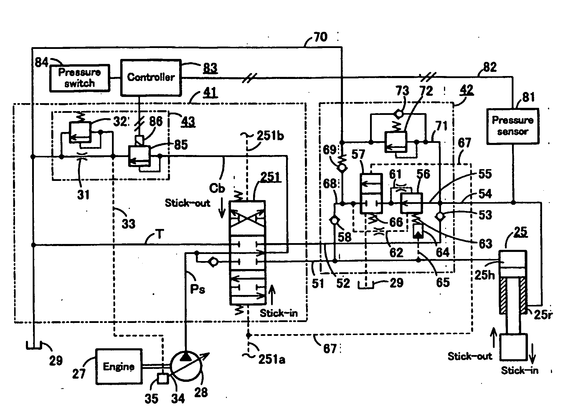
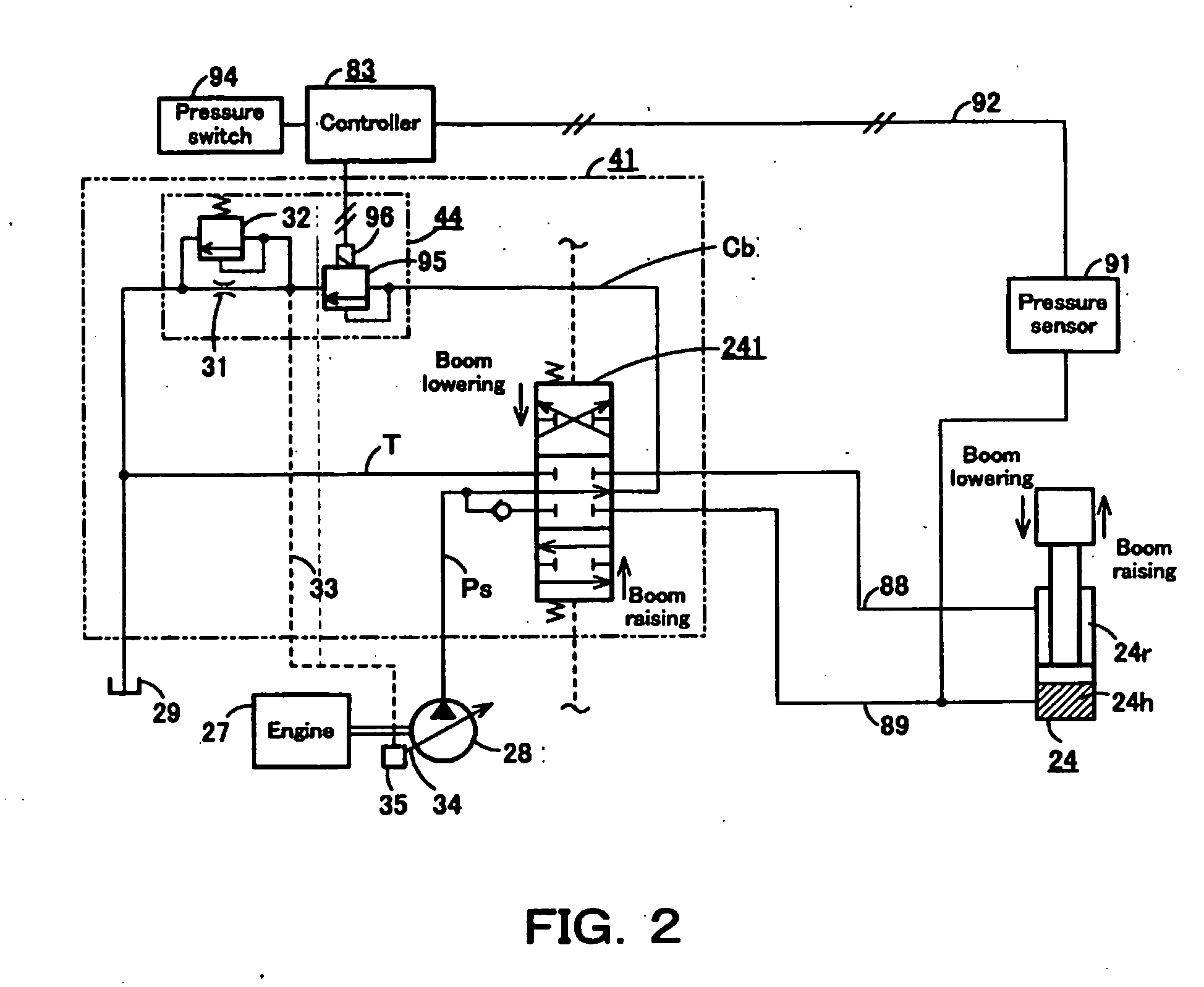
[0043]Next, the present invention is explained hereunder, referring to an embodiment thereof shown in FIGS. 1 through 4. The circuit shown in FIG. 5 is a basic circuit on which the present invention is based. The elements corresponding to those in FIG. 5 are identified with the same reference symbols, explanation of which may be omitted herein. As the circuits for the travel systems, the swing system, and the bucket system, are the same as those of the conventional circuit shown in FIG. 5, their explanations, too, are omitted.
[0044]FIGS. 1 and 2 illustrate a load pressure compensation system in a 2-pump open center system shown in FIG. 5. This load pressure compensation system is capable of partial load pressure compensation while making use of the merits of the conventional open center system, thereby improving ground leveling ability and productivity when using a heavy-weight bucket, as well as lifting-operability when hoisting a load.
[0045]In FIGS. 1 and 2, numeral 41 denotes a c...
PUM
 Abstract
Description
Claims
Application Information