Particle Separator and Method for Removing Particles from an Exhaust Gas Stream of an Internal Combustion Engine

a technology of particle separator and exhaust gas stream, which is applied in the direction of separation process, machine/engine, mechanical apparatus, etc., can solve the problems of increased fuel consumption, particle emissions, and high exhaust gas counter pressure caused by filter, and achieve the effect of easy perforation and convenient shap

Active Publication Date: 2009-12-24
MAN TRUCK & BUS AG
View PDF8 Cites 0 Cited by
  • Summary
  • Abstract
  • Description
  • Claims
  • Application Information

AI Technical Summary

Benefits of technology

[0025]The particle separator is preferably accordingly provided with means for repeatedly deflecting the exhaust gas stream in the particle separator and / or for dividing the exhaust gas stream into partial exhaust gas streams and / or for accelerating the exhaust gas stream and / or for slowing the exhaust gas stream down, in order to be able to ensure the most different requirements for particle removal in conjunction with the inventive particle separator. Various possibilities exist to accomplish this. A particularly economical construction of the particle separator results if it is formed as a plate separator composed of a plurality of separator plates that are interconnected in superimposed layers, and that form a set of plates. The differing flow regions and / or the deflection regions and / or the separation regions and / or the collection regions and / or the storage regions and / or the flow-through openings can, in this connection, viewed entirely in general be formed in a straightforward manner by material shaping and / or material deformation and / or material stamping and / or material recesses at prescribed regions of at least a portion of the separator plates of a set of plates. For this purpose, it is advantageous if at least a portion of a set of plates have an essentially identical configuration, although this is not absolutely necessary. The individual separator plates are particularly advantageously formed by foils and / or mats having a prescribed thickness. Such foils and / or mats can be very easily shaped, for example such that at least one of the foils is wave-shaped or corrugated, whereby the term “corrugated or wave-like configuration” is here to be understood in a broad sense, and in particular also includes shapings or the like that are folded or bent in an accordion-like manner. With such corrugated, for example foils, as separator plates, it is possible in combination with further separator plates embodied, for example, as foils to form in a straightforward manner the appropriately desired number and geometry of flow channels of the particle separator. By providing constrictions or indentations having the same or different corrugation or wave amplitudes (height) and / or different or the same corrugation frequencies (number of corrugations), it is possible in a relatively straightforward manner to alter the free flow cross-section and hence the flow velocity, or to achieve a deflection, or individual regions can be completely separate from the flow, in order to provide, for example, the desired storage spaces or dead zones. In this connection, it can be particularly advantageous, when viewed in the direction of flow, for successive constrictions to constrict the corrugated profile alternatingly first from the upper side and then from the underside. In addition, relative to different plate planes, the constrictions can also be offset relative to one another, for example such that the constrictions relative to adjacent plate planes are offset relative to one another by half of the spacing between the constrictions.
[0026]Furthermore, such separator plates formed by, for example, foils and / or mats can be easily perforated, thus enabling a transition into adjacent flow channels.
[0027]It is particularly advantageous to alternatingly arrange, for example foils as separator plates, with different amplitudes and / or frequencies of the corrugation or bends, so that regions having different flow cross-sections, in other words different cell densities and hence different flow velocities, result. If the foils form, for example, parallel flow channels, a smooth layer should be provided as an intermediate layer in order to prevent the corrugated foils from slipping into one another. It is, of course, also possible to alter the amplitude and / or frequency or bend along the separator plate, for example a foil.

Problems solved by technology

During combustion in a diesel engine, and also during direct injection with a spark ignition engine, emissions of particles occur that among other reasons result due to the incomplete combustion of the fuel, and predominantly comprise carbon black.
A significant drawback of such a procedure, however, is the high exhaust gas counter pressure that is caused by the filter.
This becomes noticeable by an increased fuel consumption.
In addition, during the operation non-combustible constituents are also deposited on the filter, such as lubricating oil ash.
As a result, the exhaust gas counter pressure continuously increases, so that the filter must be regularly and frequently replaced in order to avoid an even greater fuel consumption, and possibly also damage to the internal combustion engine.
Furthermore, insufficient oxidation can result in an ever increasing coating with soot, which can ultimately lead to clogging of the filter.
However, the drawback of this is that due to the constantly changing exhaust gas temperatures and the constantly changing NOx raw emissions of intermittently operated internal combustion engines, as is the case with motor vehicles, there is often insufficient NO2 available for oxidizing the removed soot.
However, the quantity of particles that can be stored in this manner is relatively small due to the small volume of the fleece.
Furthermore, the manufacture of the fleece is very expensive.

Method used


Image

  • Particle Separator and Method for Removing Particles from an Exhaust Gas Stream of an Internal Combustion Engine
  • Particle Separator and Method for Removing Particles from an Exhaust Gas Stream of an Internal Combustion Engine
  • Particle Separator and Method for Removing Particles from an Exhaust Gas Stream of an Internal Combustion Engine

Examples


Embodiment Construction

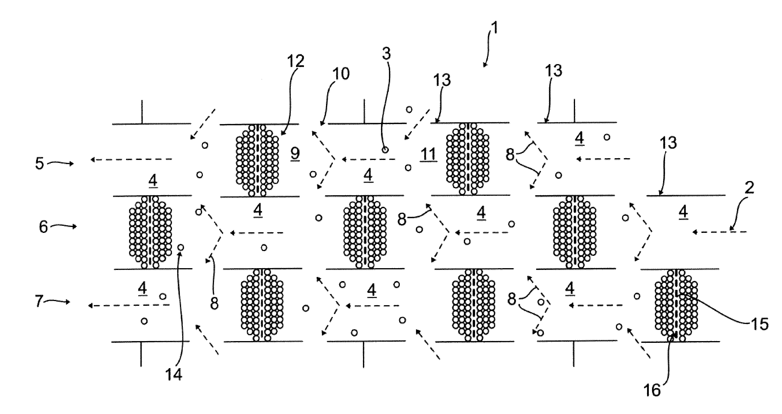
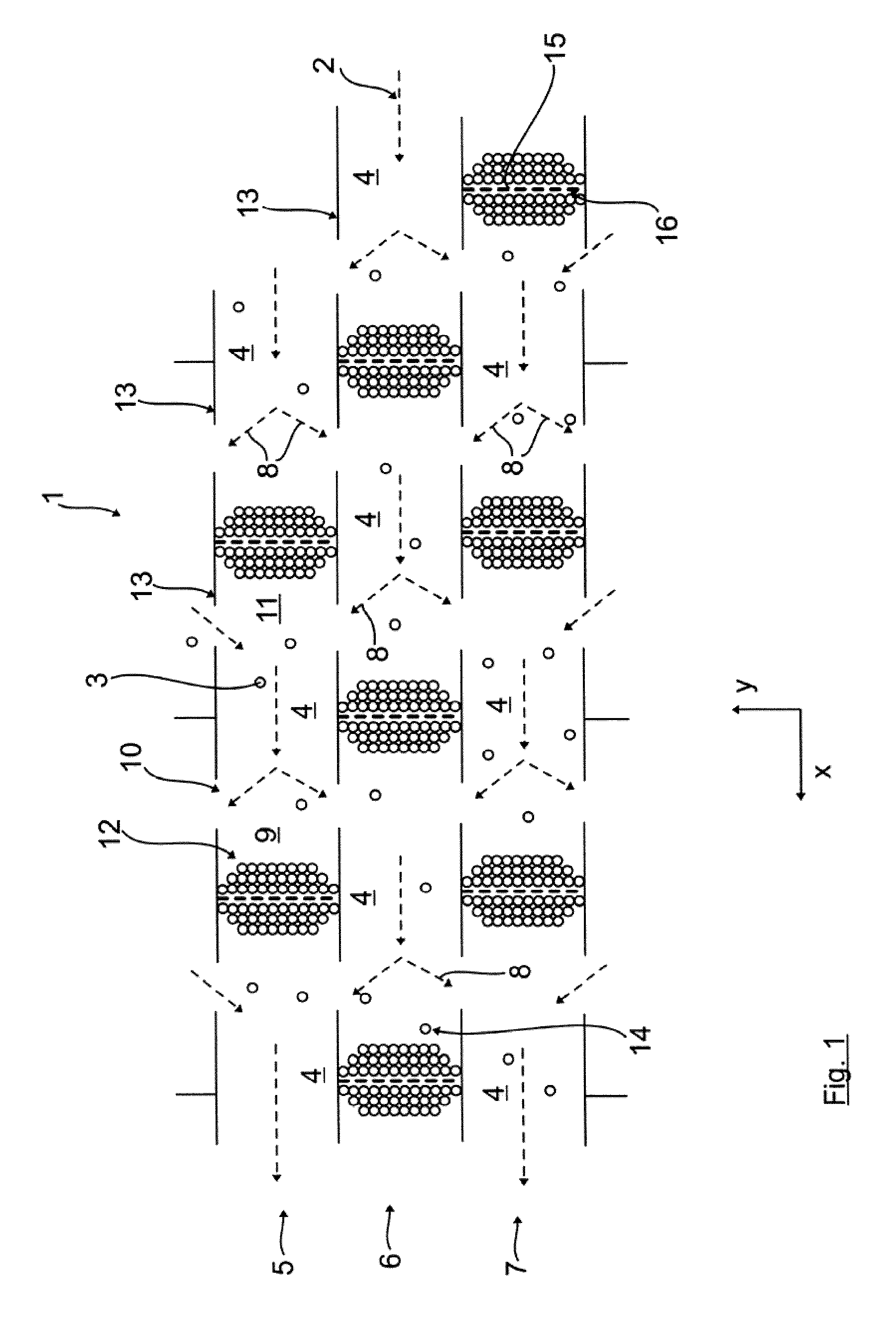
[0033]Referring now to the drawings in detail, FIG. 1 schematically shows a parallel section through at least a portion of an inventive embodiment of a particle separator 1, and hence is quasi a plan view onto a specific portion of the particle separator 1, illustrating in principle the flow of the exhaust gas stream 2 in conjunction with the separation or removal of, for example, very fine particles 3 out of the exhaust gas stream. The direction of flow x here corresponds to the main direction of flow of the overall exhaust gas stream, regardless of eventual deflections or diversions.

[0034]The particle separator 1 is provided with a plurality of flow cells 4, which are here, by way of example only embodied essentially identically. The flow cells 4 are disposed in a plurality of rows 5,6 and 7 that are arranged next to one another, and are also respectively disposed one after the other. The flow cells 4 of two adjacent rows 5, 6, 7 are offset relative to one another in such a way th...


PUM

PropertyMeasurementUnit
temperaturesaaaaaaaaaa
volumeaaaaaaaaaa

Abstract

A particle separator and method for removing particles from an exhaust gas stream of an internal combustion engine. A prescribed number of flow cells are formed in the particle separator. The exhaust gas stream flows into and/or out of the flow cells via, as viewed in a main direction of flow of the exhaust gas stream, side wall regions of the flow cells. At least one storage space is formed in the flow cells for storing particles removed from the exhaust gas stream, which flows through at least portions of the particle separator.

Description

BACKGROUND OF THE INVENTION [0001]The present invention relates to a particle separator for removing particles from an exhaust gas stream of an internal combustion engine. The present invention also relates to a method for removing particles from an exhaust gas stream of an internal combustion engine.[0002]During combustion in a diesel engine, and also during direct injection with a spark ignition engine, emissions of particles occur that among other reasons result due to the incomplete combustion of the fuel, and predominantly comprise carbon black. To bum this carbon black, GB 895,990 A proposes burning or treating them with NO2 as oxidizing agent instead of oxygen.[0003]It is furthermore known from U.S. Pat. No. 4,902,487 to separate off carbon particles at a filter, and to subsequently oxidize the particles with NO2. To produce the NO2 pursuant to DE 28 320 02, for example, the NO contained in the exhaust gas stream of the internal combustion engine can be oxidized on a platinum...

Claims


Application Information

Patent Timeline
Patent Type & Authority Applications(United States)
IPC IPC(8): F01N3/035F01N3/02F01N3/10
CPCB01D45/02Y02T10/20F01N3/021B01D45/08Y02T10/12
Inventor DORING, ANDREASTILINSKI, MARCO
Owner MAN TRUCK & BUS AG
Why Eureka
Try Eureka