
Welding wire for submerged arc welding

a welding wire and submerged arc technology, applied in welding/cutting media/materials, welding apparatus, manufacturing tools, etc., can solve the problems of short useful life of the contact tip of the welding gun through which the welding wire passes, and the inability to provide welding wire for the saw system, etc., to achieve the effect of reducing contact tip abrasion wear

Active Publication Date: 2009-12-24
LINCOLN GLOBAL INC
View PDF27 Cites 11 Cited by
  • Summary
  • Abstract
  • Description
  • Claims
  • Application Information

AI Technical Summary

Benefits of technology

[0014]In accordance with this invention, it has been found that conventional welding wire solid lubricants will work essentially as well as copper cladding in reducing contact tip abrasive wear in submerged arc welding. Thus it is possible, in accordance with this invention, to eliminate the copper waste and contamination problem normally encountered when using copper clad SAW welding wire in submerged arc welding while still maintaining the improved contact tip useful life that copper cladding enables.
[0016]In addition, the present invention also provides a process for reducing contact tip abrasive wear in submerged arc welding, the process comprising using as the welding wire a submerged arc welding wire substrate and a particulate solid lubricant on the surfaces of the welding wire substrate.

Problems solved by technology

A particular disadvantage of SAW is that only horizontal surfaces can be welded, as a practical matter, since gravity will normally cause the granular flux to slide off of non-horizontal surfaces.
Therefore, welding wire for SAW systems are not provided with the solid lubricants typically used in GMAW systems for reducing sliding friction.
In any event, because of these substantially more intense conditions in SAW, the useful life of the contact tip of the welding gun through which the welding wire passes can be very short due to friction and abrasive wear.
Unfortunately, portions of this copper cladding are often stripped off the welding wire as it passes through the knruled drive rolls (e.g., drive rolls 52 in FIG. 4) and wire straighteners typically found in a standard SAW wire feeding system.
Over time, this stripped copper can accumulate in the feeding system as copper flakes and may even contaminate the weld being formed.
This copper contamination, in turn, can jeopardize weld integrity due a phenomenon known as “copper cracking,” which is a type of liquid metal embrittlement.

Method used


Image

  • Welding wire for submerged arc welding
  • Welding wire for submerged arc welding
  • Welding wire for submerged arc welding

Examples


examples

[0046]In order to more thoroughly describe this invention, the following working examples were conducted.

[0047]In each example, a 5 / 32 inch (˜4 mm) diameter solid mild steel welding wire was welded in the flat (1F) position above a rotating mild steel pipe (30 inch diameter, 1.5 inch wall thickness). The pipe was rotated at approximately 0.8 rpm, resulting in a welding travel speed of approximately 75 inches per minute. Before welding, the surface of the pipe and the end of the contact tip were separated by a fixed 1.5 inch distance. During welding, the welding wire was fed at approximately 120 inches per minute, resulting in a welding current of approximately 1150 Amps. Welding voltage was held constant at 39 Volts. Lincolnweld 761 SAW flux was used for all welding trials.

[0048]All wires were welded for at least one hour. The contact tip wear associated with each wire was quantified by measuring the percent area increase of the contact tip bore through which the welding wire was fe...


PUM

PropertyMeasurementUnit
diameteraaaaaaaaaa
particle sizeaaaaaaaaaa
diameteraaaaaaaaaa

Abstract

The copper cladding normally applied to the surfaces of a submerged arc welding wire for preventing weld gun contact tip abrasive wear is replaced with a solid lubricant. This eliminates copper contamination of the weld from the copper cladding while preserving the useful life of the contact tip.

Description

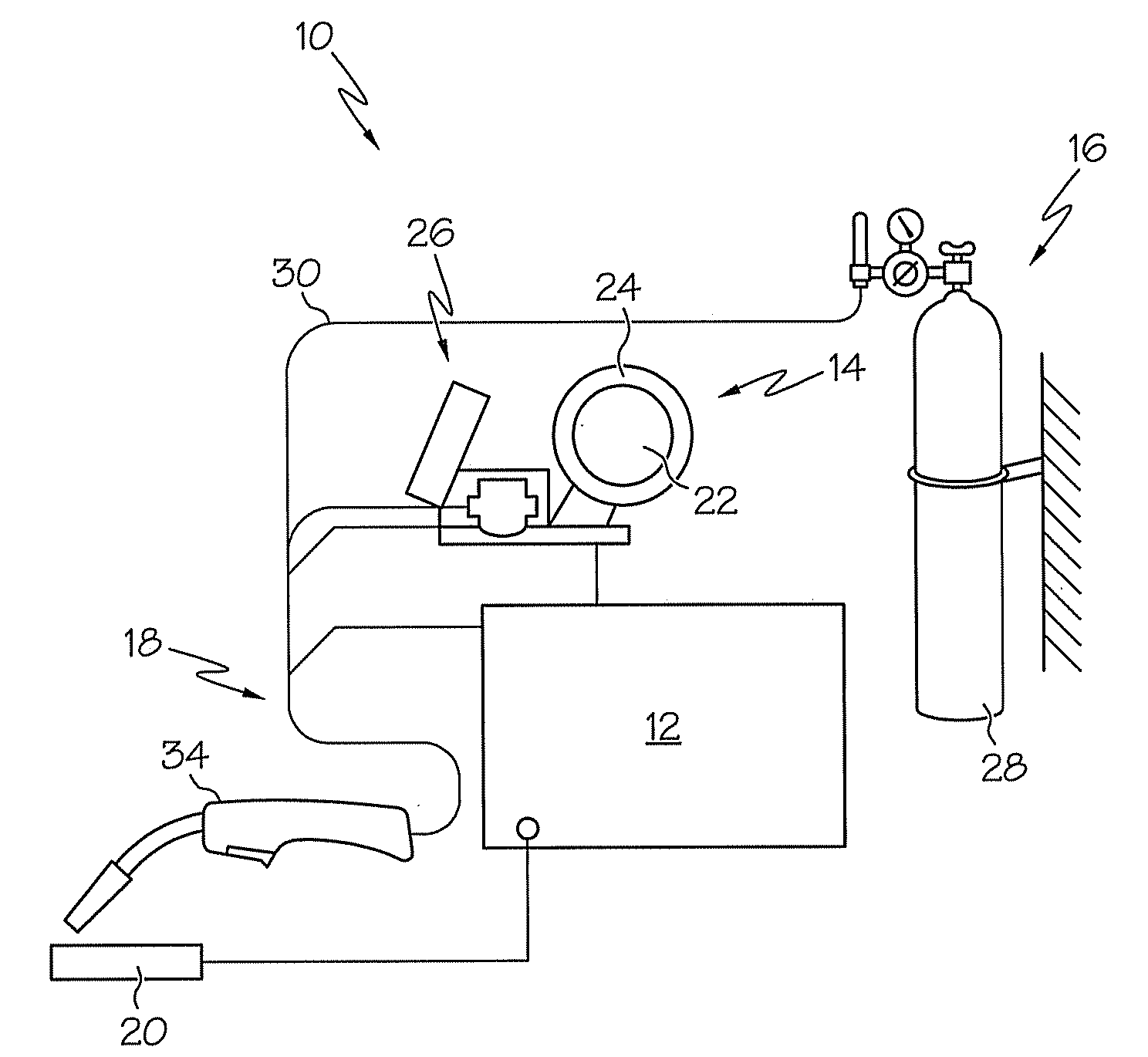
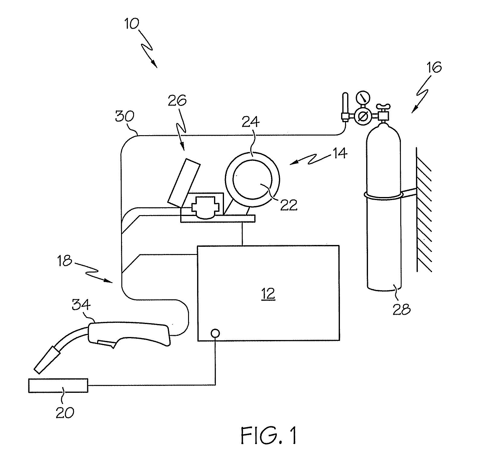
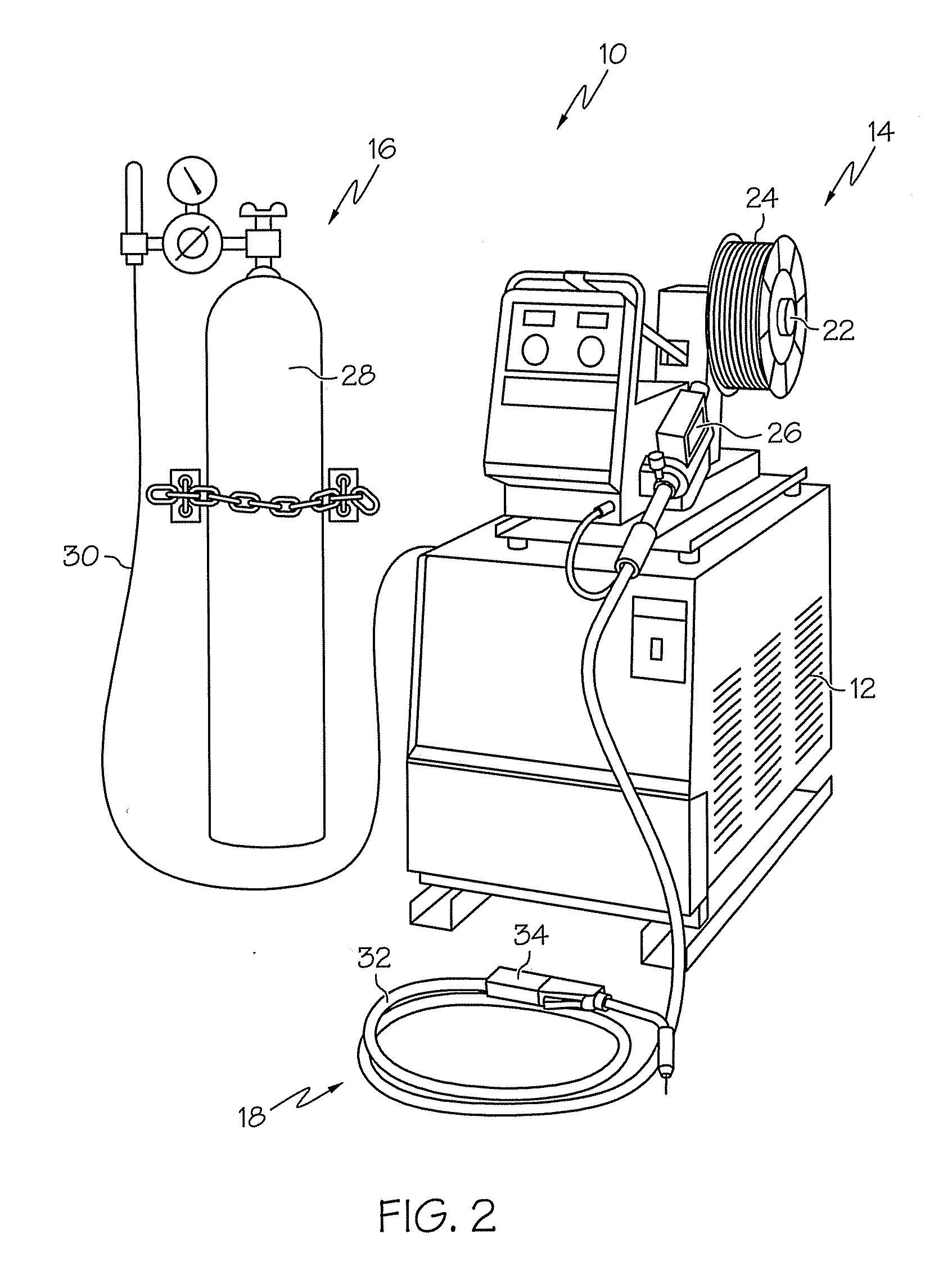
BACKGROUNDGas Metal Arc Welding[0001]Gas metal arc welding (GMAW), sometimes referred to by its subtypes metal inert gas (MIG) welding or metal active gas (MAO) welding, is a semi-automatic or automatic arc welding process in which a continuous and consumable wire electrode (“welding wire”) and a shielding gas are fed through a welding gun.[0002]FIGS. 1 and 2 illustrate the basic design of a conventional industrial GMAW system. As shown in these figures, GMAW system 10 includes electrical power source 12, wire drive assembly 14, shielding gas supply system 16, and cable assembly 18 for carrying electrical power, welding wire and shielding gas to a workpiece 20 to be welded. Wire drive assembly 14 typically includes reel stand 22 for carrying a spool 24 of a continuous, consumable wire electrode as well as drive mechanism 26 including one or more drive wheels (not shown) for driving welding wire from spool 24 through cable assembly 18 to workpiece 20. Meanwhile, shielding gas supply ...

Claims


Application Information

Patent Timeline
Patent Type & Authority Applications(United States)
IPC IPC(8): B23K33/00
CPCB23K9/186B23K2201/32B23K35/36B23K35/0211B23K2101/32
Inventor SCHAEFFER, J. BENKAHN, BORIS
Owner LINCOLN GLOBAL INC
Learn More