
Method of Producing Polarizing Plate, Polarizing Plate, and Liquid Crystal Display

a technology of polarizing plate and liquid crystal display, which is applied in the direction of polarizing elements, paper/cardboard containers, instruments, etc., can solve the problems of large-scale apparatus required to evaporate solvent, the yield of polarizing plate production tends to decrease, and the quality of the required quality has become even more critical

Inactive Publication Date: 2009-12-24
KONICA MINOLTA OPTO
View PDF4 Cites 36 Cited by
  • Summary
  • Abstract
  • Description
  • Claims
  • Application Information

AI Technical Summary

Problems solved by technology

Specifically, with the development of increased size of monitors and TV sets and of precise image reproduction, the required quality therefor has become even more critical.
However, since the cyclic olefin resin features poor moisture permeability, any solvent such as water contained in an adhesive used to laminate a polarizer tends not to be released, and therefore one side thereof has needed to be a cellulose ester-based film.
In cases in which such a polarizing plate featuring different materials on both the front and the rear side is used, a problem is noted in that the yield of producing the polarizing plate tends to decrease, whereby improvement thereof has been demanded.
From the viewpoint of enhanced uniform film thickness, a norbornene-based polymer film or a cellulose triacetate film has been commonly employed, but there have been problems that, for example, a large-scale apparatus is required to evaporate the solvent.
However, it was found that when a polarizing plate, which employs a cyclic olefin resin for one polarizing plate protective film and a cellulose resin film, produced via such a melt casting method, for the other polarizing plate protective film, was employed, the yield of the plate tended to markedly decrease.
Further, there has been noted a problem of a decrease in front contrast when the polarizing plate was used for a large liquid crystal display of more than 30 diagonal inches.

Method used


Image

  • Method of Producing Polarizing Plate, Polarizing Plate, and Liquid Crystal Display
  • Method of Producing Polarizing Plate, Polarizing Plate, and Liquid Crystal Display
  • Method of Producing Polarizing Plate, Polarizing Plate, and Liquid Crystal Display

Examples


example of synthesis 1

Synthesis of Illustrated Compound A-1

[0512]After heating 24.6 g (0.116 mol) of 3,4,5-trimethoxybenzoic acid, 100 ml of toluene and 1 ml of N—N-dimethylformamide to 60° C., 15.2 g (0.127 mol) of thionyl chloride was slowly added dropwise, and this mixture was heated at 60° C. for two hours. Then 15.1 g (0.127 mol) of 4-cyanophenol dissolved previously into 50 ml of acetonitrile was slowly added dropwise into this solution. After that, the solution was heated and stirred at 60° C. for 3 hours, and the reaction solution was cooled down to the room temperature. Then ethyl acetate and water were used to perform liquid separation, and sodium sulfate was used to remove water from the organic phase having been obtained. The solvent was distilled off under reduced pressure, and 100 ml of acetonitrile was added to the solid having been obtained, thereby recrystallizing the mixture. The acetonitrile solution was cooled down to the room temperature, and the crystal having been precipitated was ...

example of synthesis 2

Synthesis of Illustrated Compound A-2

[0516]After heating 106.1 g (0.5 mol) of 2,4,5-trimethoxybenzoic acid, 340 ml of toluene and 1 ml of dimethylformamide to 60° C., 65.4 g (0.55 mol) of thionyl chloride was slowly added dropwise, and this mixture was heated for 2 hours at 65° C. through 70° C. Then 71.5 g (0.6 mol) of 4-cyanophenol previously dissolved into 150 ml of acetonitrile was slowly added dropwise into this solution. After that, the solution was heated and stirred at 80° C. through 85° C. for 2 hours, and the reaction solution was cooled down to the room temperature. Then ethyl acetate (1 L) and water were used to perform liquid separation, and sodium sulfate was used to remove water from the organic phase having been obtained. Approximately 500 ml of solvent was distilled off under reduced pressure, and 1 L of methanol was added to the solid having been obtained, thereby recrystallizing the mixture. The crystal having been precipitated was recovered by filtration, whereby...

example of synthesis 3

Synthesis of Illustrated Compound A-3

[0520]After heating 10.1 g (47.5 mM) of 2,3,4-trimethoxybenzoic acid, 40 ml of toluene and 0.5 ml of dimethylformamide to 80° C., 6.22 g (52.3 mM) of thionyl chloride was slowly added dropwise, and this mixture was heated and stirred for 2 hours at 80° C. Then 6.2 g (52.3 mM) of 4-cyanophenol previously dissolved into 20 ml of acetonitrile was slowly added dropwise into this solution. After that, the solution was heated and stirred at 80° C. through 85° C. for 2 hours, and the reaction solution was cooled down to the room temperature. Then ethyl acetate and water were used to perform liquid separation, and sodium sulfate was used to remove water from the organic phase having been obtained. The solvent was distilled off under reduced pressure, and 50 ml of methanol was added, thereby recrystallizing the mixture. The crystal having been precipitated was recovered by filtration, whereby 11.9 g (yield 80%) of the target compound was obtained as a whi...


PUM

PropertyMeasurementUnit
Linear densityaaaaaaaaaa

Abstract

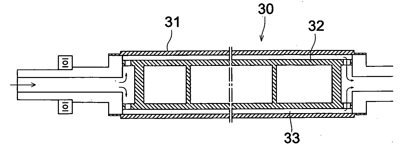
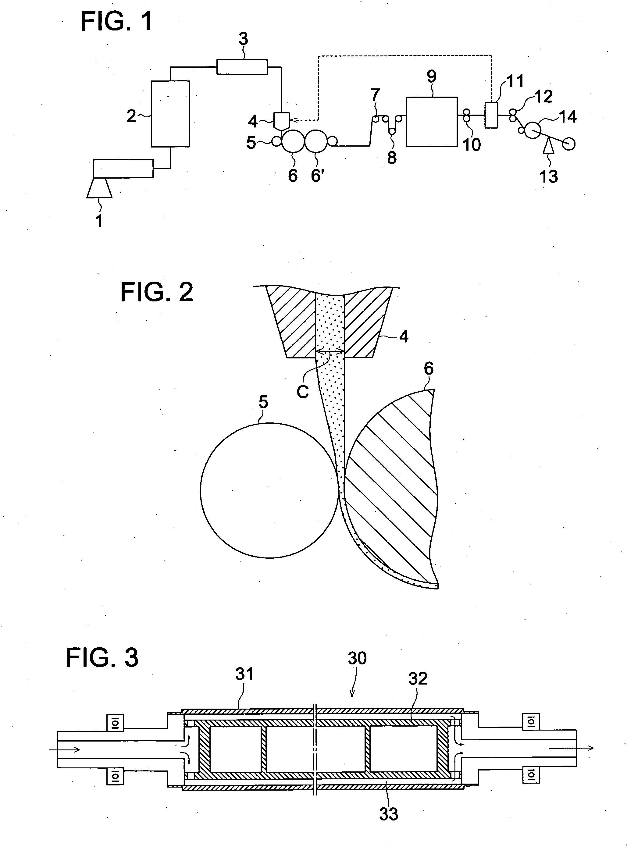
Disclosed is a method for producing a polarizing plate including the steps of: laminating a polarizing plate protective film A on one side of a polarizer; and laminating a polarizing plate protective film B on the other side of the polarizer, wherein the polarizing plate protective film B contains a noncrystalline polyolefin resin; and the polarizing plate protective film A is a solidified film produced in such a manner that a melted film prepared by extruding a melted substance containing a cellulose resin from a die is conveyed while pressed against a cooling roll by a touch roll so as to have a draw ratio of 10 to 30 and to be solidified on the cooling roll, provided that the touch roll has an outer metal cylinder, an inner metal cylinder and a space formed therebetween for accommodating a cooling medium.

Description

TECHNICAL FIELD[0001]The present invention relates to a method of producing a polarizing plate, the polarizing plate, and a liquid crystal display, and more specifically an object of the present invention is to prevent any decrease in the yield of the polarizing plate when types of protective films arranged on both sides of a polarizing film differ, as well as to provide a liquid crystal display exhibiting significantly improved front contrast and having reduced display non-uniformity.BACKGROUND ART[0002]Liquid crystal displays have been widely used as monitors due to their small footprint and low energy consumption features, compared to old-fashioned CRT displays, and have become common in application of TV sets. For such liquid crystal displays, various optical films such as polarizing films, retardation films, antireflection films, brightness enhancement films are used.[0003]In a polarizing film, a cellulose ester film is laminated to one or both sides of a polarizer composed of ...

Claims


Application Information

Patent Timeline
IPC IPC(8): G02F1/1335G02B5/30B32B37/00B29C48/08B29C48/305B29C48/92
CPCB29C47/0021B29C47/14B29C47/8845Y10T156/10B29K2105/256G02B1/105G02B5/3033B29C47/886B29C2948/92704B29C48/08B29C48/305B29C48/91B29C48/914B29C48/9155B29C2948/92152B29C2948/92428B29C2948/92438B29C2948/92523B29C2948/92647B29C2948/92895B29C2948/92904B29C2948/92923B29C2948/92933G02B1/14G02B5/30B29C48/30B29C48/92
Inventor YAJIMA, TAKATOSHIKUREMATSU, MASAYUKIMURAKAMI, TAKASHI
Owner KONICA MINOLTA OPTO
Learn More