Electrochemical energy source, and method for manufacturing of such an electrochemical energy source

a technology of electrochemical energy source and electrochemical energy source, which is applied in the direction of cell components, sustainable manufacturing/processing, and final product manufacturing, etc., can solve the problems of reducing the capacity of said energy source, and re-crystallizing of adjacent active layers already deposited on the substrate, so as to achieve stable electrochemical energy source, prevent degradation of adjacent active layers, and facilitate overheating

Inactive Publication Date: 2009-12-24
KONINKLIJKE PHILIPS ELECTRONICS NV
View PDF2 Cites 22 Cited by
  • Summary
  • Abstract
  • Description
  • Claims
  • Application Information

AI Technical Summary

Benefits of technology

[0004]This object can be achieved by providing an electrochemical energy source according to the preamble, characterized in that each active layer of the stack which is deposited prior to a subsequent active layer of the stack has a higher annealing temperature than the annealing temperature of the subsequent active layer. It has been found that the degradation of active layers in conventional energy sources known from the prior art, is often caused during deposition, in particular during annealing (also known as curing), of an active layer at a relatively high annealing temperature which may easily overheat, and consequently degrade adjacent active layers already deposited onto the substrate and annealed at a relatively low annealing temperature. This overheating of active layers of the stack deposited earlier may result in decomposition of these layers, allowing these layers to react with other adjacent layers to form detrimental interfacial layers with inferior properties, and / or allowing these layers to (re)crystallize to form phases with undesired properties. By gearing the annealing temperatures of the different active layers, and hence the active layers as such, into a successive order, degradation of these active layers can be prevented in a relatively efficient manner. According to the invention, the deposition order of the different active layers of the stack of the electrochemical energy source according to the invention is dictated by the order of the successive annealing temperatures, or temperature ranges, of the active layers to obtain a relatively stable electrochemical energy source having a relatively reliable performance, and which be manufactured in a relatively reliable manner. During manufacturing of the energy source according to the invention this means in general that the active layer deposited firstly can be deposited and / or annealed at any temperature (as long as the substrate allows it). The subsequent active layer of the stack shall be deposited / annealed at a temperature lower, and preferably significantly lower (about 50° C.), than the first active layer, and so on. This inherently means that the final active layer of the stack shall be deposited at the lowest temperature. Commonly, the annealing process is considered as being a (final) part of the deposition process of an active layer, wherein each active layer has its own optimum annealing temperature, or annealing temperature range, with which this active layer will acquire the specific material properties needed to function properly in the battery stack. Besides the critical deposition order which is applied to the electrochemical energy source according to the invention, preferably the materials of the different active layers are mutually chemically stable and compatible. A reaction between two chemically incompatible materials should preferably be avoided at any (annealing) temperature to secure a durable and adequate functioning of the electrochemical energy source according to the invention.

Problems solved by technology

It has been found that the degradation of active layers in conventional energy sources known from the prior art, is often caused during deposition, in particular during annealing (also known as curing), of an active layer at a relatively high annealing temperature which may easily overheat, and consequently degrade adjacent active layers already deposited onto the substrate and annealed at a relatively low annealing temperature.
This overheating of active layers of the stack deposited earlier may result in decomposition of these layers, allowing these layers to react with other adjacent layers to form detrimental interfacial layers with inferior properties, and / or allowing these layers to (re)crystallize to form phases with undesired properties.
This crystalline silicon substrate suffers from the drawback that the intercalating species diffuse relatively easily into said substrate, resulting in a reduced capacity of said energy source.

Method used


Image

  • Electrochemical energy source, and method for manufacturing of such an electrochemical energy source
  • Electrochemical energy source, and method for manufacturing of such an electrochemical energy source

Examples


Embodiment Construction

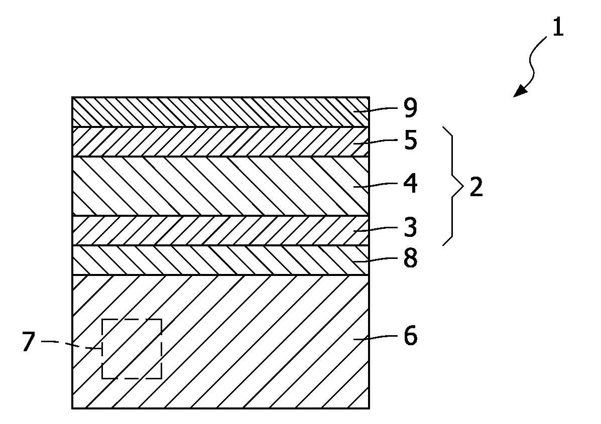
[0016]FIG. 1 shows a schematic cross section of an electrochemical energy source 1 known from the prior art. An example of the electrochemical energy source 1 shown in FIG. 1 is also disclosed in the international patent application WO2005 / 027245. The known energy source 1 comprises a lithium ion battery stack 2 of an anode 3, a solid-state electrolyte 4, and a cathode 5, which battery stack 2 is deposited onto a conductive substrate 6 in which one or more electronic components 7 are embedded. In this example the substrate 6 is made of doped silicon, while the anode 3 is made of amorphous silicon (a-Si). The cathode 5 is made of LiCoO2, and the solid-state electrolyte is made of LiNbO3. Between the battery stack 2 and the substrate 6 a lithium barrier layer 8 is deposited onto the substrate 6. In this example, the lithium diffusion barrier layer 8 is made of tantalum. The conductive tantalum layer 8 acts as a chemical barrier, since this layer counteracts diffusion of lithium ions (...


PUM

PropertyMeasurementUnit
temperatureaaaaaaaaaa
temperaturesaaaaaaaaaa

Abstract

An electrochemical energy source, comprising: a substrate, and at least one stack deposited onto said substrate, the stack comprising at least the active layers: an anode, a cathode, and an intermediate solid-state electrolyte separating said anode and said cathode. An electronic device provided with an electrochemical energy source according to the invention and a method for the manufacturing of an electrochemical source according to the invention.

Description

FIELD OF THE INVENTION[0001]The invention relates to an electrochemical energy source, comprising: a substrate, and at least one stack deposited onto said substrate, the stack comprising at least the active layers: an anode, a cathode, and an intermediate solid-state electrolyte separating said anode and said cathode. The invention also relates to an electronic device provided with an electrochemical energy source according to the invention. The invention further relates to a method for the manufacturing of an electrochemical source according to the invention, comprising the step of: A) depositing at least one stack deposited onto a substrate, the stack comprising at least the following active layers: an anode, a cathode, and an intermediate solid-state electrolyte separating said anode and said cathode.BACKGROUND OF THE INVENTION[0002]Electrochemical energy sources based on solid-state electrolytes are known in the art. These (planar) energy sources, or ‘solid-state batteries’, eff...

Claims


Application Information

Patent Timeline
Patent Type & Authority Applications(United States)
IPC IPC(8): H01M14/00H01M4/02H01M4/48H01M6/04H01M4/82H01M4/52
CPCH01M2/1066H01M4/525Y10T29/49115H01M10/0436H01M10/38H01M6/40Y02E60/10Y02P70/50
Inventor NIESSEN, ROGIER ADRIANUS HENRICANOTTEN, PETRUS HENRICUS LAURENTIUS
Owner KONINKLIJKE PHILIPS ELECTRONICS NV
Why Eureka
Try Eureka