Ejector for fuel cell system

a fuel cell and system technology, applied in the direction of machines/engines, process and machine control, instruments, etc., can solve the problems of deterioration of the movable core duration, difficulty in fuel gas supply for the fuel cell, collision noise and vibration, etc., and achieve the effect of reducing size and weigh

Inactive Publication Date: 2009-12-24
KEIHIN CORP
View PDF5 Cites 51 Cited by
  • Summary
  • Abstract
  • Description
  • Claims
  • Application Information

AI Technical Summary

Benefits of technology

[0014]The general object of the present invention is to provide an ejector for a fuel cell system that secures a stable discharge rate of fuel gas from a nozzle within a variable flow rate range, and the primary purpose of the present invention is to provide an ejector for a fuel cell system (hereinafter also referred to as only an “ejector”) that realizes reduction in size and weight.

Problems solved by technology

By the way, it has been pointed out that because, in such a fuel cell system using an ejector, each diameter of a nozzle and a diffuser that are included in the ejector is fixed, it is difficult to supply fuel gas for the fuel cell in accordance with various driving situations (e.g. various driving situations through an idling driving to a high speed driving) of a fuel cell vehicle including the fuel cell system.
In addition, in the above fluid supply apparatus for a fuel cell, the first and second switch valves are electromagnetic valves having each solenoid, so that when a movable core attracted to a fixed core due to excitation of the solenoids, or when the movable core returns to its original position when the solenoid becomes unexcited, the movable core collides against the fixed core of magnetic material or other metal members and may generate collision noises and vibrations.
If an electromagnetic valve with a horizontally-installed solenoid is employed in order to reduce a vertical size of the overall ejector apparatus, when a movable core is attracted to a fixed core in the horizontal direction due to excitation of the solenoids, or when the movable core returns in the horizontal direction to its original position when the solenoid becomes unexcited, the axis of the movable core becomes deviated in the vertical direction due to its own weight in a clearance around the sliding part thereof so that friction against other members becomes greater, which may cause a problem of deterioration of the movable core duration.

Method used


Image

  • Ejector for fuel cell system
  • Ejector for fuel cell system
  • Ejector for fuel cell system

Examples


Embodiment Construction

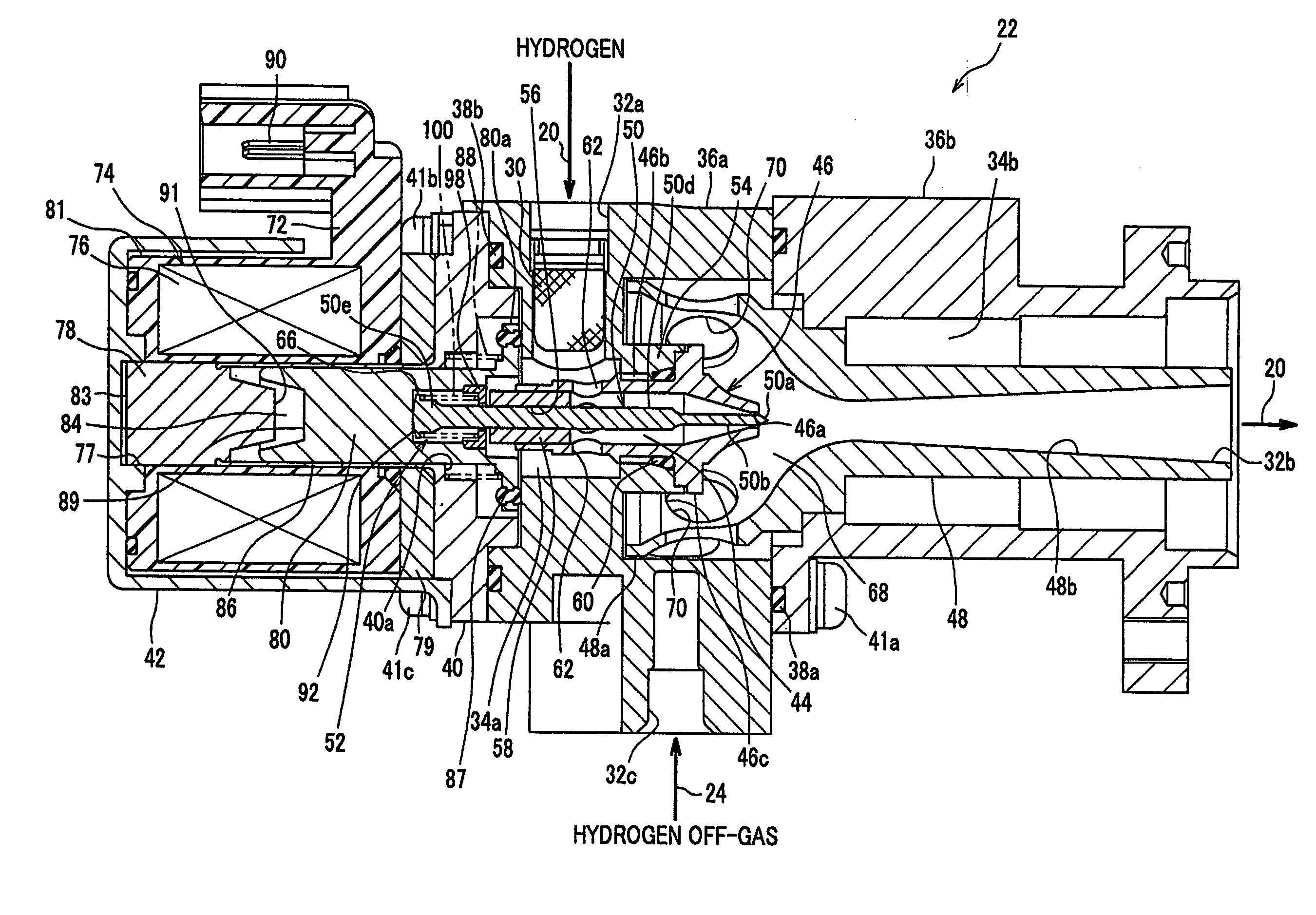
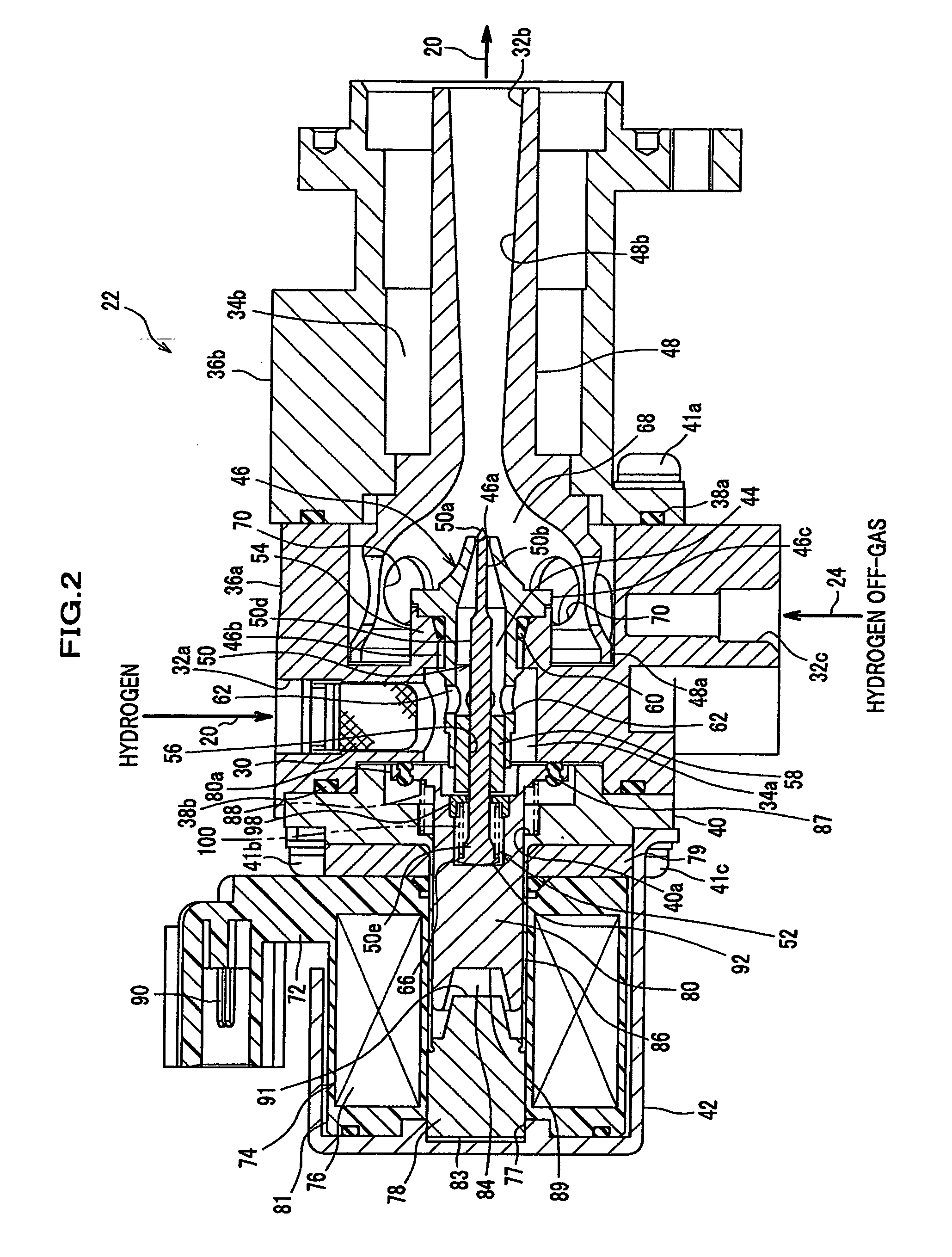
[0051]Detailed descriptions will be provided on an embodiment of the present invention, with reference to the attached drawings.

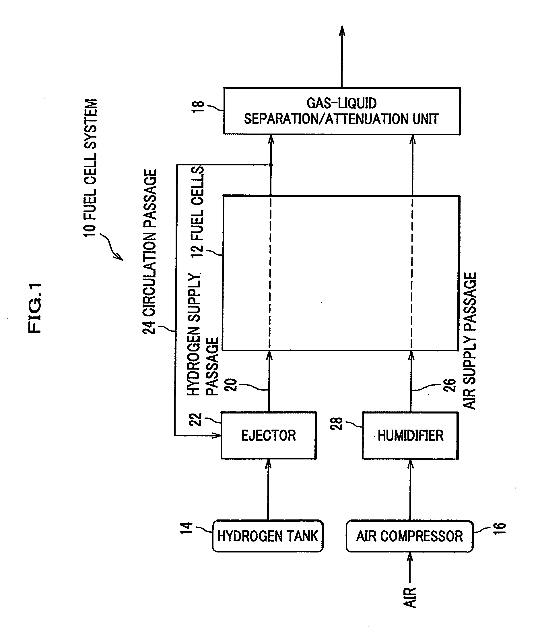
[0052]As shown in FIG. 1, the fuel cell system 10 includes a fuel cell 12, a hydrogen tank (also referred to as a “fuel gas supply means”) 14 that is charged with high pressured hydrogen gas and supplies the hydrogen gas as fuel gas for the fuel cell 12, an air compressor 16 that supplies compressed air including oxidant gas (oxygen) for the fuel cell 12, a gas-liquid separation / attenuation unit 18 that separates un-reacted hydrogen into gas (hydrogen) and liquid (water) and also attenuates the separated hydrogen with un-reacted air discharged from the fuel cell 12.

[0053]The fuel cell 12 may be a polymer electrolyte fuel cell (PEFC), for example, and is installed in a vehicle such as a fuel cell vehicle. The fuel cell 12 have a stack body including a plurality of stacked single cells (not shown), and also has an anode that is supplied with hydrogen as fuel ...


PUM

PropertyMeasurementUnit
angleaaaaaaaaaa
areaaaaaaaaaaa
inner diameteraaaaaaaaaa

Abstract

An ejector for a fuel cell system of the present invention includes a nozzle having a nozzle hole for discharging hydrogen supplied via an inlet port of an ejector body, a diffuser for mixing hydrogen discharged from the nozzle hole and hydrogen off-gas discharged and returned via a circulation passage from a fuel cell, a needle displacing in the axial direction by a driving force of a solenoid, and a bearing member held in a hollow portion of the nozzle, and having a through hole that movably supports the needle in the axial direction.

Description

CROSS-REFERENCE TO RELATED APPLICATION[0001]This application claims the foreign priority benefit under 35 U.S.C. § 119 of Japanese Patent Application No. 2008-155187 filed on Jun. 13, 2008, Japanese Patent Application No. 2008-155189 filed on Jun. 13, 2008; Japanese Patent Application No. 2008-157085 filed on Jun. 16, 2008; and Japanese Patent Application No. 2008-157089 filed on Jun. 16, 2008 the disclosures of which are incorporated herein by reference.BACKGROUND OF THE INVENTION[0002]1. Field of the Invention[0003]The present invention relates to an ejector used for a fuel cell system including a fuel cell.[0004]2. Description of the Related Art[0005]Recently, there have been many developments regarding a fuel cell vehicle having a fuel cell such as a polymer electrolyte fuel cell (PEFC). In such a fuel cell vehicle, a motor is rotated by power generated by the fuel cell so as to drive the vehicle.[0006]In general, the fuel cell includes stacks of a plurality of single cells. Eac...

Claims


Application Information

Patent Timeline
Patent Type & Authority Applications(United States)
IPC IPC(8): H01M8/04F04F5/20
CPCF04F5/18F04F5/36Y02E60/50H01M8/04089F04F5/463H01M8/04097Y10T137/2572
Inventor YAMADA, KOUICHIFUKUMA, KAZUNORIWADA, MAKOTO
Owner KEIHIN CORP
Why Eureka
Try Eureka