[0010]According to an aspect of the present invention, an ejector for improved
operability of a PDE is disclosed. The ejector includes an inlet section and an outlet section. The inlet section is fluidly coupled to both a primary fluid flow source emanating from the PDE and a secondary fluid flow source. The outlet section is in fluid communication with the inlet section, and is configured such that the movement of a primary fluid through it promotes entrainment of a secondary fluid through the inlet section. In such capacity, the ejector acts as a pump to introduce the secondary fluid into the primary fluid
stream being exhausted from the PDE.
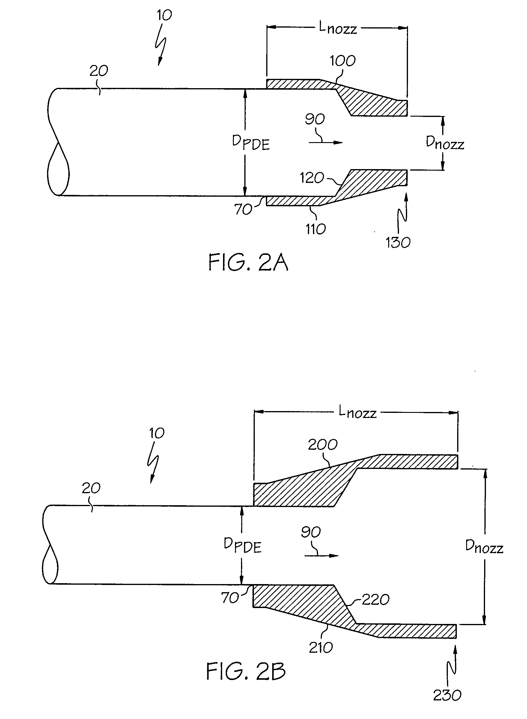
[0011]Optionally, the outlet section can be configured to define a converging, diverging or substantially straight flow path. In addition, the outlet section can define either a substantially axisymmetric fluid flow path or a non-axisymmetric flow path, the latter for example configured as a substantially two-dimensional fluid flow path. In the present context, the term “substantially” is utilized to represent the inherent degree of uncertainty that may be attributed to any quantitative comparison, value, measurement, or other representation. As such, it refers to an arrangement of elements or features that, while in theory would be expected to exhibit exact correspondence or behavior, may in practice embody something slightly less than exact. The term also represents the degree by which a quantitative representation may vary from a stated reference without resulting in a change in the basic function of the
subject matter at issue. In another option, the inlet section may include a contoured lip to avoid the onset of separated flow along the ejector inlet section. Moreover, the length of the ejector relative to the ejector
diameter may be configured to fall within a preferred ratio, such as between three and four. It will be appreciated by those skilled in the art that the
diameter is a convenient measure of the ejector flow path size, defining an equivalent exit area in the ejector's outlet section. Thus, even if the outlet section is not of axisymmetric shape, an equivalent
diameter exits based on the exit area. It will further be appreciated that other area ratios are contemplated, and may be formed based on the operational needs of the PDE. Other such area ratios are within the scope of the present invention. In yet another option, an ejector intermediate section may be disposed between the inlet and outlet sections, thereby increasing the overall length of the ejector.
[0015]In yet another option, an aircraft (alternately referred to as an air vehicle) employing a PDE is disclosed. In the present context, an aircraft is any manned or unmanned vehicle that through a combination of aerodynamic surfaces, propulsion and flight control components is capable of sustained flight. As with the previous aspects of the invention, the PDE may include ejectors, nozzles or combinations of the two in order to improve its performance, as well as that of an aircraft incorporating the PDE. The ejector or
nozzle features are preferably integrated into the aircraft design to optimize air vehicle performance.
[0016]According to yet another aspect of the present invention, a pulse
detonation engine including a
detonation chamber, exhaust structure and one or more engine
performance enhancement devices is disclosed. As with the previous aspects, the detonation chamber is configured to generate a time-varying primary fluid, while the exhaust structure accepts a primary fluid that is generated by the detonation chamber. The engine
performance enhancement device includes one or both of a nozzle and an ejector, and is fluidly coupled to the exhaust structure so that when the exhaust (in the form of the time-varying primary fluid) passes through the device, at least one performance parameter of the pulse detonation engine is enhanced. Such performance parameter may include increased thrust, decreased
noise or lower temperature of the fluid passing through the engine
performance enhancement device.
[0017]According to still another aspect of the present invention, a method of operating a PDE is disclosed, where the configuration of the PDE includes a detonation chamber configured to contain a primary fluid and a thrust enhancement device fluidly coupled to the detonation chamber. The method includes generating a detonation wave in the detonation chamber and flowing a primary fluid through the thrust enhancement device such that thrust produced by both the thrust enhancement device and the detonation chamber can be used to enhance
operability of the PDE.
[0021]According to still another aspect of the present invention, a method of reducing the
noise produced by an operating PDE is disclosed. The configuration of the PDE can be as previously described, where specifically the thrust enhancement device comprises one or both of an exhaust nozzle disposed downstream of the detonation chamber and an ejector. Optionally, the exhaust nozzle may be configured to define a converging or diverging flow path, where a particular embodiment incorporates a converging nozzle with an
area ratio in the converging nozzle is between 0.5 and 0.8, preferably approximately 0.6. As with the previous aspect of the invention, a fill fraction may be defined in the detonation chamber, where filling the detonation chamber with a mixture of a fuel and an oxidant in accordance with the fill fraction can be used to optimize performance. An ejector similar to that described in the previous aspects may also be fluidly coupled to the exhaust nozzle to provide
noise reduction, cooling or thrust augmentation.

