Method of bubbling a gas into a glass melt

Inactive Publication Date: 2009-12-31
CORNING INC
View PDF17 Cites 35 Cited by
  • Summary
  • Abstract
  • Description
  • Claims
  • Application Information

AI Technical Summary

Benefits of technology

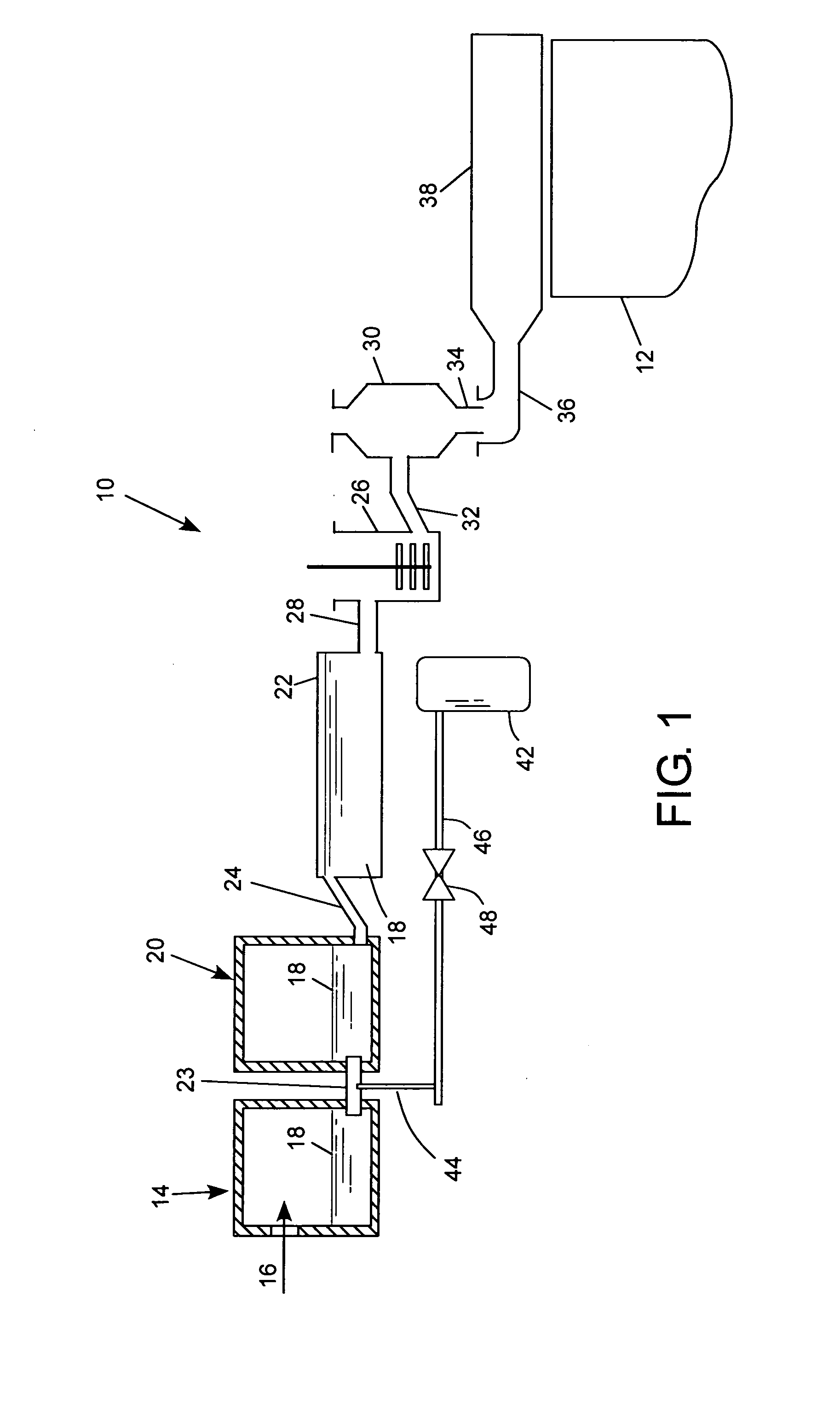
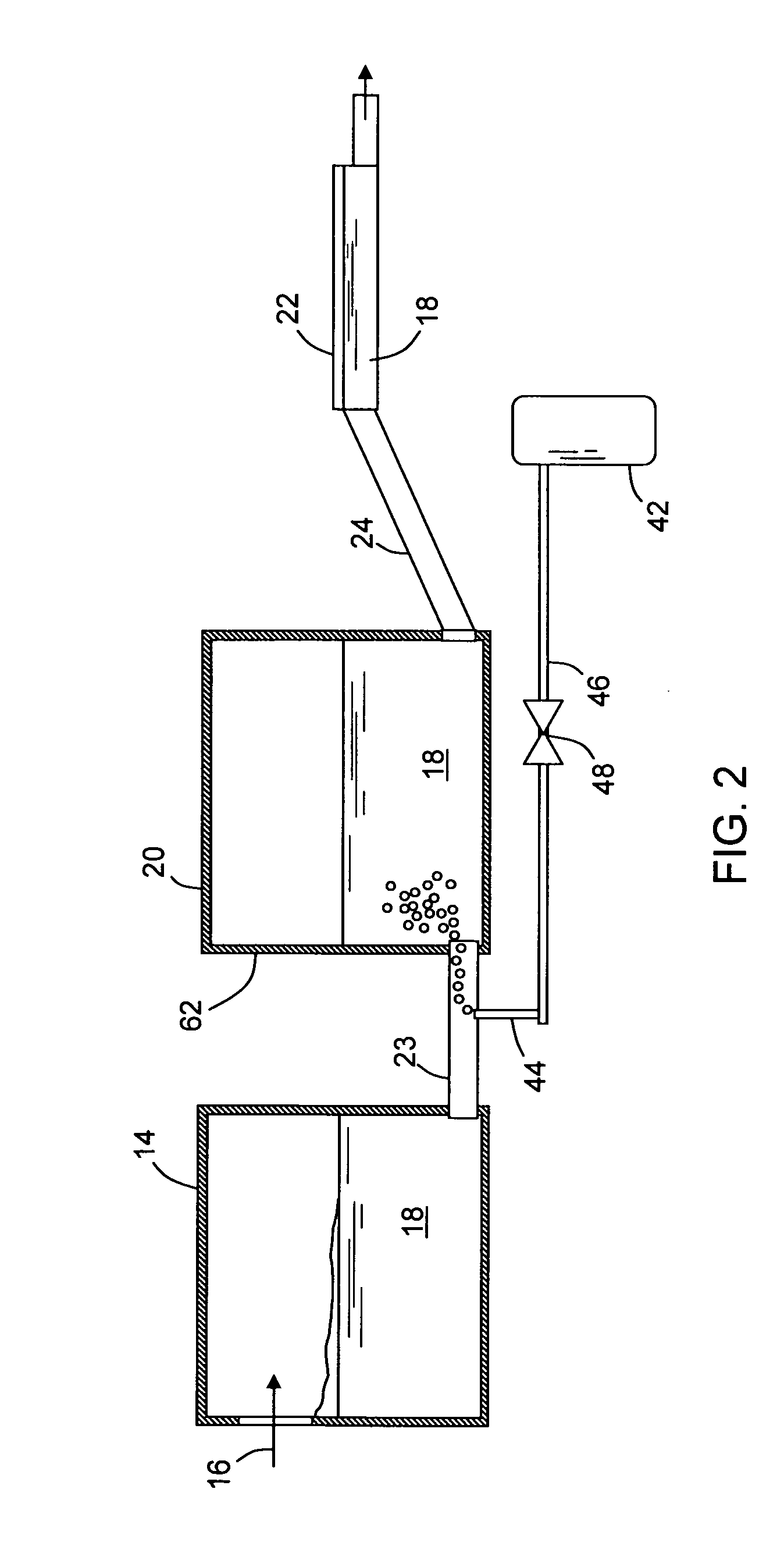
[0015]In certain embodiments, a second tube may connect the second vessel to a third vessel, and the molten glass is flowed between the second and the third vessel via this second connecting tube. The third vessel may, for example, be a fining tube, wherein a temperature of the molten glass is raised to a temperature higher than the temperature of the molten glass during the melting stage in the first vessel. The oxygen containing gas may be introduced into the glass melt through the second connecting tube, prior to the entry of the molten glass into the fining tube. Thus, a method of introducing a gas into a molten glass is described comprising heating a feed material to form a molten glass in a first vessel, flowing the molten glass to a second vessel through a first refractory metal tube, flowing the molten glass from the second vessel through a second refractory metal tube to a third vessel, introducing a gas comprising oxygen into the molten glass in one or both of the first or second refractory metal tubes. That is, the gas may be introduced (b

Problems solved by technology

Another recurring issue in the glass melting and forming process is producing glass that is well mixed.
Inhomogeneities in the molten glass, such as chemical and density inhomogeneities, can result in streaks and cord in the glass, that may be visually unappealing and for some applications unacceptable.
Arsenic-containing compounds are generally toxic, and processing of glass with arsenic results not only in manufacturing wastes that are expensive to process, but also creates disposal issues relative to the display device itself after the useful life of the device is exhausted.
Unfortunately, many alternative fining agents typically release less oxygen, and/or at too low a temperature, and reabsorb too little O2 during the conditioning process relative to established fining agents such as arsenic, thereby limiting their fining and oxygen re-absorption capabilities.
Thus, during the fining stage of the glass production process (i.e. while the glass is within the fining vessel), the fining agent may

Method used


Image

  • Method of bubbling a gas into a glass melt
  • Method of bubbling a gas into a glass melt
  • Method of bubbling a gas into a glass melt

Examples


Embodiment Construction

[0025]In the following detailed description, for purposes of explanation and not limitation, example embodiments disclosing specific details are set forth to provide a thorough understanding of the present invention. However, it will be apparent to one having ordinary skill in the art, having had the benefit of the present disclosure, that the present invention may be practiced in other embodiments that depart from the specific details disclosed herein. Moreover, descriptions of well-known devices, methods and materials may be omitted so as not to obscure the description of the present invention. Finally, wherever applicable, like reference numerals refer to like elements.

[0026]In a typical glass making process raw feed materials are heated in a furnace (melter) to form a viscous mass, or glass melt. Furnaces are generally constructed from refractory blocks comprised of burned flint clay, sillimanite, zircon or other refractory (high temperature) material. While small furnaces may b...


PUM

PropertyMeasurementUnit
Temperatureaaaaaaaaaa
Flow rateaaaaaaaaaa
Viscosityaaaaaaaaaa

Abstract

Feed materials are melted in a furnace to form a glass melt in a first vessel, transferred through a first refractory metal connecting tube to a second vessel for conditioning, then transferred through a second refractory metal connecting tube to a third vessel where the glass melt is fined. A gas is bubbled into the glass melt through an injection tube disposed in the first connecting tube, optionally in the second connecting tube, and optionally in both connecting tubes. The gas may be used to mix the melt and/or recharge a fining agent with oxygen.

Description

BACKGROUND OF THE INVENTION[0001]1. Field of the Invention[0002]This invention is directed to a method of forming a molten glass, and in particular for introducing a gas into a glass melt for the purpose of mixing and fining the molten glass. The invention is particularly useful for fining high melting temperature or high strain point glasses, such as those that are used for glass substrates for flat panel display devices.[0003]2. Technical Background[0004]Liquid crystal displays (LCDs) are flat panel display devices that include flat glass substrates or sheets. The fusion process is a preferred technique used to produce sheets of glass used in LCDs because the fusion process produces sheets whose surfaces have superior flatness and smoothness without the need for subsequent polishing compared to sheet produced by other methods. The fusion process is described, for example, in U.S. Pat. Nos. 3,338,696 and 3,682,609, the contents of which are incorporated herein by reference.[0005]Co...

Claims


Application Information

Patent Timeline
IPC IPC(8): C03B5/16
CPCC03B5/193C03B5/18C03B5/225
Inventor JOHNSON, WILLIAM WESTON
Owner CORNING INC
Why Eureka
Try Eureka