Color image display device

a display device and color image technology, applied in the field of color image display devices, can solve the problems of high gamut, low ntsc ratio, difficult to obtain a display with high color reproducibility, etc., and achieve high color reproducibility, easy adjustment of white balance, and without impairing image brightness

Inactive Publication Date: 2009-12-31
MITSUBISHI CHEM CORP
View PDF8 Cites 33 Cited by
  • Summary
  • Abstract
  • Description
  • Claims
  • Application Information

AI Technical Summary

Benefits of technology

[0038]According to the color image display device of the present invention, it is possible to provide a color image display device whereby reproduction of deep red and green is realized without impairing the brightness of an image even by a LED backlight; a high color reproducibility as a whole image can be accomplished; emission of red, green and blue is carried out by one chip, whereby the productivity will not be impaired by its mounting; and yet adjustment of the white balance is easy.

Problems solved by technology

Inversely, if the brightness is increased, the NTSC ratio tends to be low, and it tends to be difficult to reproduce a vivid image.
However, in the above light source, the phosphor was yellow, whereby emission with wavelength unnecessary from the viewpoint of the color purity of red and green was substantial, and it was difficult to obtain a display with high color reproducibility (High Gamut).
Here, it is at least in principle possible to increase the color purity of red and green by cutting off light with unnecessary wavelength by means of a color filter, but as mentioned above, if it is attempted to increase the NTSC ratio by adjusting the color filter in order to reproduce the vivid color image, the majority of emission of the backlight will be cut off, whereby there has been a problem that the brightness decreases substantially.
Especially, by this method, emission of red decreases substantially, whereby it has been practically impossible to reproduce a strongly reddish color.
However, in such a color image display device, LED chips independent for red, green and blue, respectively, are combined, whereby is there have been problems such that 1) it takes time and labor to mount them, 2) since the respective LED chips for red, green and blue are disposed at finite distances, it is required to take the distance of a light guide plate to be long to sufficiently mix emitted lights from the respective LED chips, and 3) since the white chromaticity is adjusted by combining the integral multiple of the respective LED chips, adjustment of the white balance can not be continuously carried out.

Method used


Image

  • Color image display device
  • Color image display device
  • Color image display device

Examples


preparation example 1

(1-1) Preparation Example 1

Preparation of Backlight 1 (BL-1)

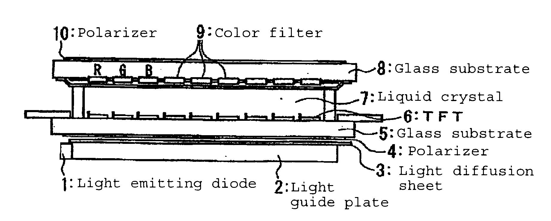
[0355]A light-emitting device is prepared by the following procedure.

[0356]A blue light emitting diode having a peak emission wavelength of 454 nm is bonded to a cup bottom surface of a frame by die bonding, and then, the light emitting diode and the frame electrode are connected by wire bonding.

[0357]As a green-emitting phosphor, BSS is used, and as a red-emitting phosphor, CASN is used. These phosphors are kneaded into an epoxy resin to obtain a paste, which is applied and cured on the light emitting diode in the cup.

[0358]Then, a cyclic polyolefin type resin sheet (trade name “ZEONOR” manufactured by ZEON CORPORATION) of wedge shape, which has a size of 289.6×216.8 mm and a thicknesses varying along the direction of the short side between a maximum thickness of 2.0 mm and a minimum thickness of 0.6 mm, is used as a light guide, and a light source comprised of the above-mentioned light emitting diode is placed along the t...

preparation example 2

(1-2) Preparation Example 2

Preparation of Backlight 2 (BL-2)

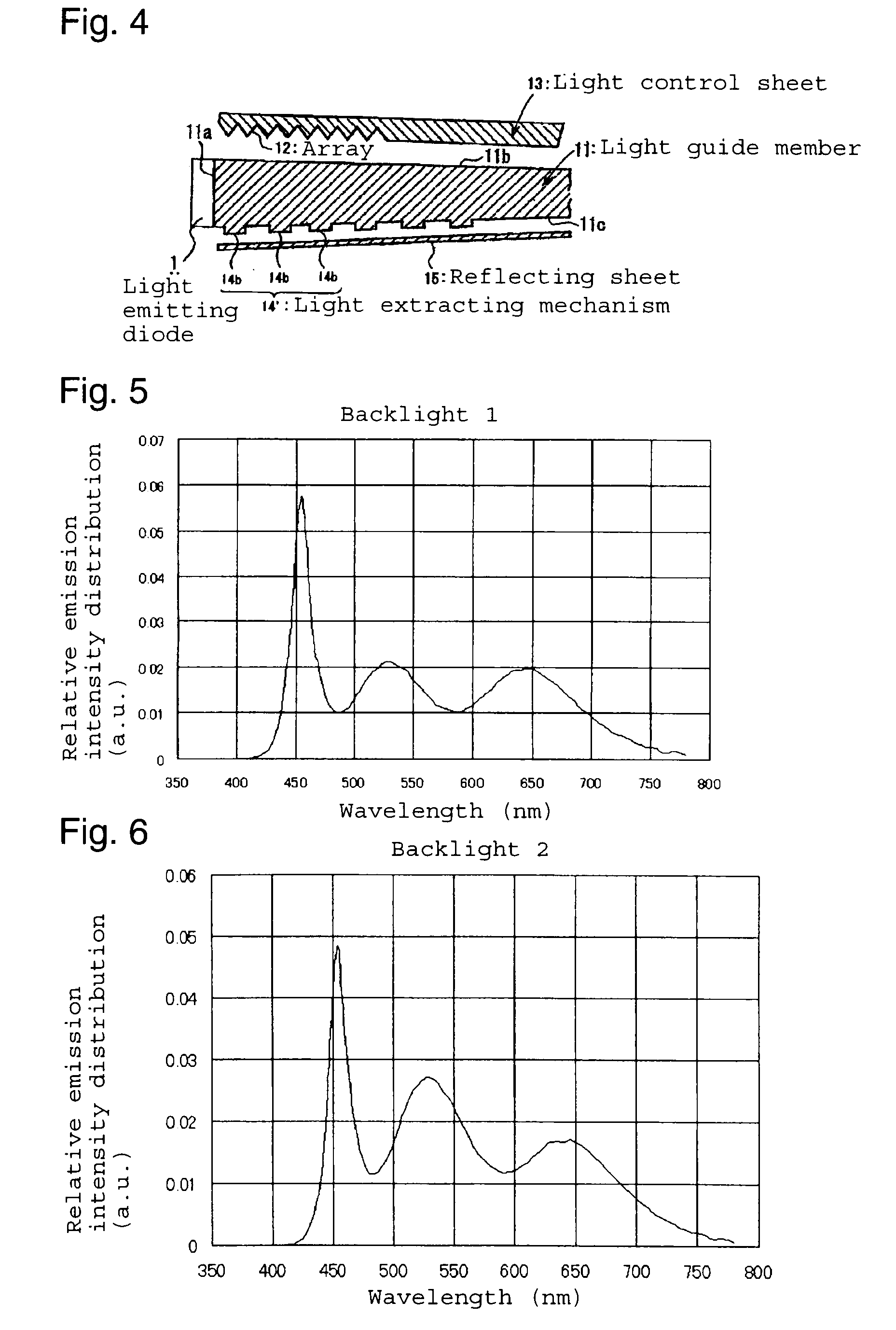
[0363]A Backlight 2 (BL-2) is Prepared in the Same Manner as in Preparation Example 1 except that in Preparation Example 1, the compounding ratio of BSS and CASN is changed to bring about an emission spectrum as shown in FIG. 5. As shown in FIG. 5, the backlight 2 has one emission peak wavelength in each of the wavelength regions of 455 nm, 531 nm and 639 nm.

preparation example 3

(1-3) Preparation Example 3

Preparation of Backlight 3 (BL-3)

[0364]A backlight 3 (BL-3) is prepared in the same manner as in Preparation Example 1 except that in Preparation Example 1, the compounding ratio of BSS and CASN is changed to bring about an emission spectrum as shown in FIG. 6. As shown in FIG. 6, the backlight 3 has one emission peak wavelength in each of the wavelength regions of 455 nm, 531 nm and 641 nm.


PUM

PropertyMeasurementUnit
wavelengthaaaaaaaaaa

Abstract

To attain a high color reproducibility as a whole image without impairing the brightness of the entire image.A color image display device comprising a combination of light shutters, a color filter having color elements of at least three colors of red, green and blue corresponding to the light shutters, and a backlight for transmission illumination, wherein a light source to be used for the backlight comprises a combination of a blue or deep blue LED and a phosphor, and the relationship between the NTSC ratio W as a color reproduction range of the color image display element and the light use efficiency Y is represented Y≧0.38W+51 (wherein W≧87).

Description

TECHNICAL FIELD[0001]The present invention relates to a color image display device. Particularly, it relates to a color image display device to realize an image having a high color purity corresponding to the emission wavelength of an improved LED backlight.BACKGROUND ART[0002]In recent years, the liquid crystal display elements are expected to be useful not only in the conventional application to personal computer monitors but also in application to ordinary color televisions. The color reproduction range of the color liquid crystal display elements is determined by colors of light emitted from the red, green and blue pixels and, where chromaticity points of the respective color pixels in the CIE XYZ calorimetric system are represented by (xR, yR), (xG, yG) and (xB, yB), the color reproduction range is represented by an area of a triangle defined by these three points on an x-y chromaticity diagram. Namely, the larger the area of this triangle, the more vivid color image the displa...

Claims


Application Information

Patent Timeline
Patent Type & Authority Applications(United States)
IPC IPC(8): G02F1/13357G02F1/1335
CPCG02B6/0043G02B6/0053G02F1/133617G02B6/0073G02B6/0055
Inventor KAWANA, SHINKANEDA, HIDEAKIKIJIMA, NAOTOSAKO, NAOKIENDOU, NORIKO
Owner MITSUBISHI CHEM CORP
Why Eureka
Try Eureka