Apparatus and method for a continuous rapid thermal cycle system

a rapid thermal cycle and apparatus technology, applied in the direction of specific use bioreactors/fermenters, enzymology, after-treatment of biomass, etc., can solve the problems of inability to easily and quickly adapt devices, inconvenient production of mass quantities of dna, and inconvenient production of devices, etc., to achieve easy adaptability to different pcr reactions, low cost, and efficient

Active Publication Date: 2009-12-31
MARSHALL UNIV RES
View PDF0 Cites 62 Cited by
  • Summary
  • Abstract
  • Description
  • Claims
  • Application Information

AI Technical Summary

Benefits of technology

[0011]The present invention comprises an apparatus and method for a continuous thermal cycle system capable of the bulk production of DNA strands that is efficient, scalable, easily adaptable to different PCR reaction requirements, and is relatively inexpensive to produce. An embodiment of the present invention has a plurality of temperature-controlled sectors within a temperature control body, thereby resulting in a plurality of temperature zones. A fluid preferably flows continuously through or along the apparatus via a path, and thereby through or along the different temperature zones.
[0012]A preferred embodiment of the present invention is particularly suited for amplification of DNA fragments quickly, easily, and in large quantities. Mass production of DNA at rates much greater than conventional DNA production rates is thereby effectively achieved using the present invention. Low manufacturing costs and enhanced scalability of the present invention permit relatively inexpensive, continuous amplification of DNA in bulk quantities. In particular, a preferred embodiment of the present invention comprises a single cylindrical temperature control body having twelve pie-shaped or wedge-shaped sectors, each sector having a means for obtaining a desired temperature, and each sector separated from other sectors by a thermal barrier. A grooved channel circles or spirals around the exterior surface of the temperature control body, and a length of tubing placed in or on the channel conveys DNA amplification reactants cyclically from one sector to subsequent sectors. The reactants are thereby exposed to different temperature zones in a cyclical fashion, ultimately resulting in the amplification of the DNA. A means for moving the reactants establishes the flow rate of the reactants through the length of tubing to optimize the amplification via PCR based upon the characteristics of the specific reactants. Any number of sectors may be incorporated into the temperature control body by simply dividing it into additional sectors or reducing the number of sectors. Also, further adaptability can be incorporated into the temperature control body by adding layered sectors and / or using a temperature control body having a shape other than a cylinder.

Problems solved by technology

This process is time intensive, labor intensive, and inefficient, as the tubes must be individually filled with the reactants, closed, processed through the automatic cycler, opened, and finally drained of the reaction product that contains the desired amplified DNA.
This device is not designed to produce mass quantities of DNA.
Moreover, the Corbett et al. device is not designed to be easily and quickly adaptable to different PCR reaction requirements.
Modifying the device for different reaction conditions therefore requires re-wrapping the tubing around one or more of the cylinders a different number of times, unwrapping the tubing around one or more of the cylinders to replace one or more of the cylinders with different cylinders, re-routing the tubing around the cylinders in different orders, or another such labor-intensive procedure.
Additionally, efficiency and fine temperature control is reduced as the reaction mixture pockets pass from one cylinder to the next and thermal energy is unintentionally lost or gained at such “gaps.”
This device is not designed for easy modification for providing a number of different reaction conditions, as additional water baths would have to be prepared and added for such modification.

Method used


Image

  • Apparatus and method for a continuous rapid thermal cycle system
  • Apparatus and method for a continuous rapid thermal cycle system
  • Apparatus and method for a continuous rapid thermal cycle system

Examples


example

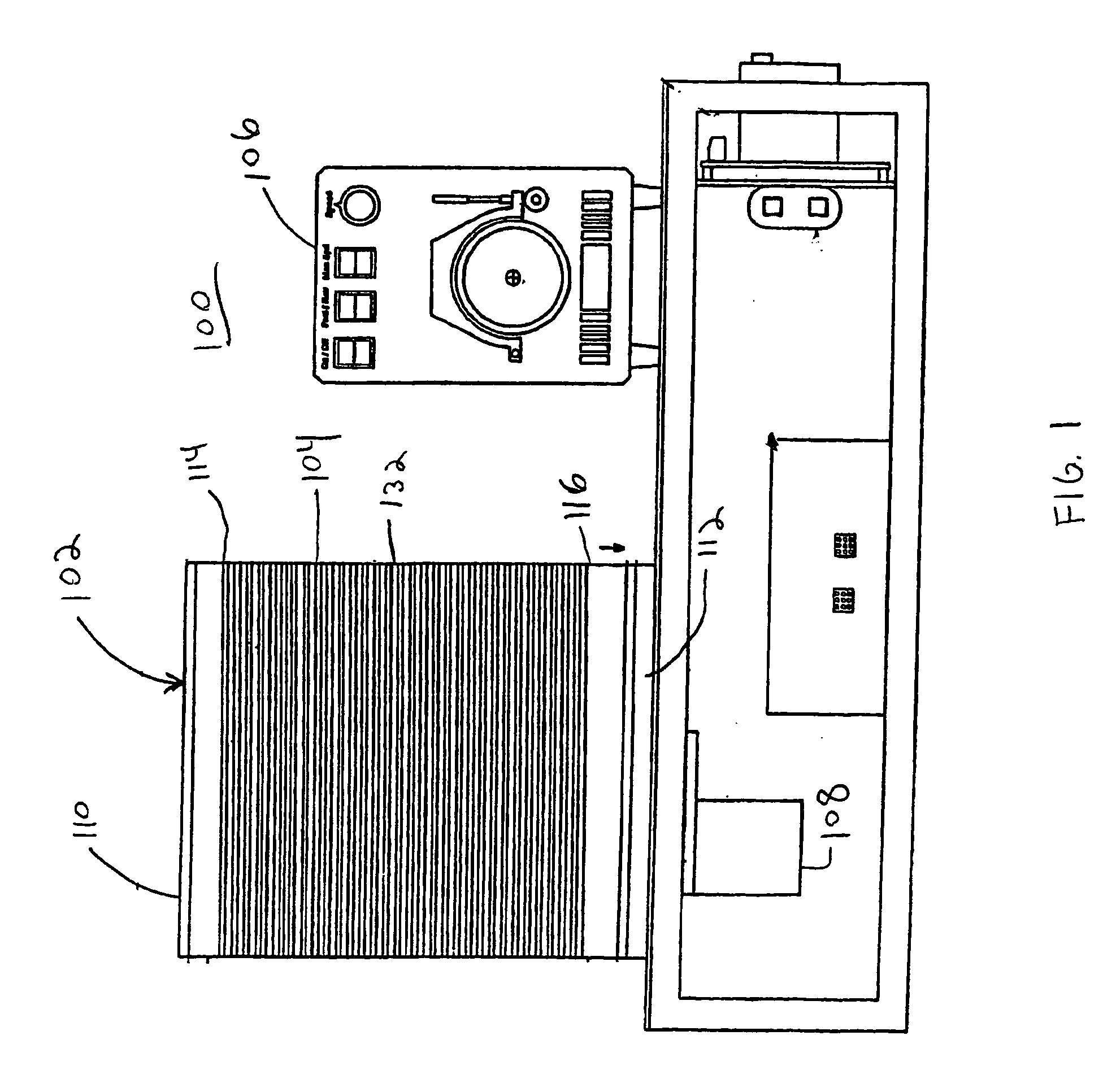
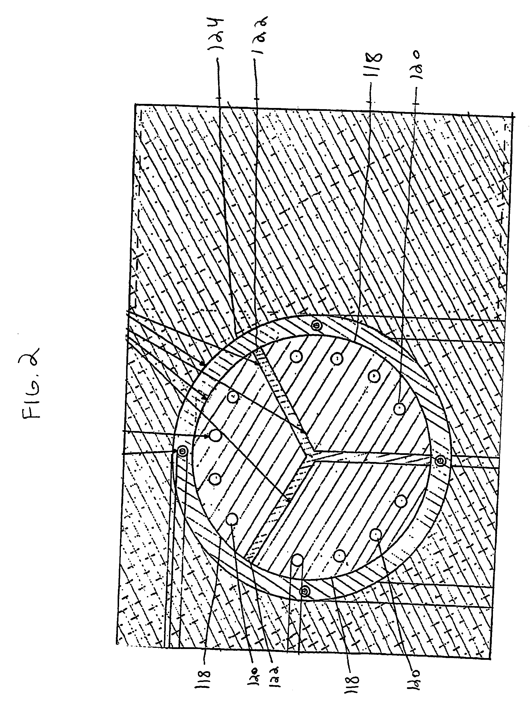
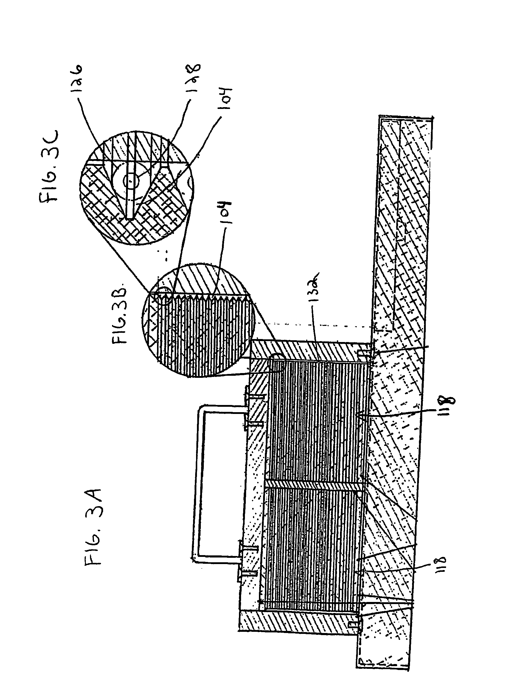
[0044]A sample was prepared containing: 12% MgCl2 (25 mM), 0.33% Taq DNA polymerase (5 units / μl), 2.0% dNTP's (deoxyadenosine triphosphate (dATP), deoxycytidine triphosphate (dCTP), deoxyguanosine triphosphate (dGTP) and deoxythymidine triphosphate (dTTP)), 8.0% template (2 μg / ml), 61.66% Pluronic F108 solution (1.5% solution), 4% forward primer, 4% reverse primer, 8% reaction buffer (10× concentration). The solution can be scaled up to the correct volume using these figures. The twelve vertical sectors 118 of the cylindrical temperature control body 102 were heated to three different temperatures, four adjacent sectors 118 were heated to 95° C., another four adjacent sectors 118 were heated to 59° C., and the final four adjacent sectors 118 were heated to 72° C. 1 / 32″ ID, 1 / 16″ OD TEFLON PTFE tubing was wrapped around the temperature control body 102 thirty times to subject the length of tubing 126 and reaction mixture to the three different temperatures thirty different times in s...


PUM

PropertyMeasurementUnit
concentrationaaaaaaaaaa
temperaturesaaaaaaaaaa

Abstract

A thermal cycle system and method suitable for mass production of DNA comprising a temperature control body having at least two sectors. Each sector has at least one heater, cooler, or other means for changing temperature. A path traverses the sectors in a cyclical fashion. In use, a piece of tubing or other means for conveying is placed along the path and a reaction mixture is pumped or otherwise moved along the path such that the reaction mixture is repetitively heated or cooled to varying temperatures as the reaction mixture cyclically traverses the sectors. The reaction mixture thereby reacts to form a product. In particular, polymerase chain reaction reactants may continuously be pumped through the tubing to amplify DNA. The temperature control body is preferably a single aluminum cylinder with a grooved channel circling around its exterior surface, and preferably has wedge-shaped or pie-shaped sectors separated by a thermal barrier.

Description

CROSS-REFERENCE TO RELATED APPLICATIONS[0001]This application claims the benefit of U.S. Provisional Application No. 60 / 540,225 filed Jan. 28, 2004.STATEMENT REGARDING FEDERALLY SPONSORED RESEARCH OR DEVELOPMENT[0002]The U.S. Government has a paid-up license in this invention and the right in limited circumstances to require the patent owner to license others on reasonable terms as provided for by the terms of Award No. 0314742 awarded by the National Science Foundation.BACKGROUND OF THE INVENTION[0003]1. Field of the Invention[0004]The present invention relates to systems for maintaining multiple temperature regions, and in particular, to a device and associated method for the automated, bulk thermal cycling of fluids, solutions, and / or reactants.[0005]2. Description of the Related Art[0006]The polymerase chain reaction (PCR) is widely used by research professionals around the world as a means to amplify small strands of DNA. Typically, PCR is performed using automated thermal cycl...

Claims


Application Information

Patent Timeline
Patent Type & Authority Applications(United States)
IPC IPC(8): C12P19/34C12M1/00
CPCB01L7/525B01L2300/0838B01L2300/0841B01L2300/1805Y10S435/809B01L2300/1827B01L2300/1883B01L2400/0487B01L2300/1822
Inventor GREGG, DEREK A.MURRAY, ELIZABETH E.NORTON, MICHAEL L.SWICK, JUSTIN T.TESSER, HERBERT
Owner MARSHALL UNIV RES
Why Eureka
Try Eureka