Reagent Delivery System, Dispensing Device and Container for a Biological Staining Apparatus

a technology of biological staining apparatus and delivery system, which is applied in the direction of analytical glassware, instruments, and chemical indicators, can solve the problems of insufficient efforts to automate sample processing, time-consuming protocol, and inability to fully address the needs of automated sample processing system, so as to eliminate cross contamination, stable form, and control the effect of accuracy

Active Publication Date: 2009-12-31
AGILENT TECH INC
View PDF64 Cites 57 Cited by
  • Summary
  • Abstract
  • Description
  • Claims
  • Application Information

AI Technical Summary

Benefits of technology

[0046]The present invention further provides a method of aspirating and dispensing reagents onto a plurality of samples on carriers (tissue slides) characterised by aspirating a plurality of predetermined volumes of a predetermined reagent, further characterised by aspirating a predetermined amount of air between each of the predetermined volumes of a reagent, in such a manner that every volume of the plurality of volumes is separated from neighboring volumes by air bubbles. In this manner, the plurality of predetermined volumes may be dispensed very accurately onto a plurality of slides.
[0047]According to this method, the probe tubing having aspirated a predefined volume of a first reagent may be removed from the first reagent container, aspirate a predetermined amount of air, forming an air gap or bubble inside the tubing, and then enter into a second reagent container and aspirate the second reagent. The air bubble separates the two reagents and the meniscus of the bubble acts as a wiper within the inner tubing wall to eliminate cross contamination between these two distinct fluids. In similar manner, a plurality of different reagents may be aspirated and separated by air during a single period in which the robotic head locates the probe over the reagent section of the stainer. Afterwards, the computer controlled robotic head can move the probe to the section with the slides, and, during the following period, dispense one or more reagents onto a single or a plurality of slides, possibly requiring different reagents.
[0048]In a preferred embodiment of the invention, the internal diameter of the tubing is 1.5 mm ( 1 / 16 inch). The small internal diameter allows for the air bubble to maintain a stable form as it moves in the tubing. Each single bubble will stay as a single entity and not break up into multiple bubbles; neither can it collapse with any other bubble. This behavior means that the amount fluid to be dispensed may be controlled accurately, even when a plurality of fluid volumes have been aspirated by the probe. The possibility of aspirating a plurality of separated volumes allows for a fast dispensing of the fluids onto one or a plurality of slides in the staining section.

Problems solved by technology

Previously, in some applications, these steps may have been performed manually, potentially creating a time-intensive protocol and necessitating personnel to be actively involved in the sample processing.
However, such previous efforts may have not fully addressed the needs for an automated sample processing system.
Previous efforts to automate sample processing may be deficient in several aspects that prevent more robust automated sample processing, such as: the lack of sufficient computer control and monitoring of sample processing; the lack of information sharing for processing protocol and processing status, especially for individual samples; the lack of diagnostic capabilities; and the lack of real-time or adaptive capabilities for multiple sample batch processing.
Past efforts at automated sample processing for samples presented on carriers such as slides, such as U.S. Pat. No. 6,352,861 to Ventana Medical Systems, Inc. and U.S. Pat. No. 5,839,091 to LabVision Corporation, have not afforded the various advantages and other combinations of features as presented herein.

Method used


Image

  • Reagent Delivery System, Dispensing Device and Container for a Biological Staining Apparatus
  • Reagent Delivery System, Dispensing Device and Container for a Biological Staining Apparatus
  • Reagent Delivery System, Dispensing Device and Container for a Biological Staining Apparatus

Examples


example

Specification for Precision

[0103]CV<10% at 100 μl and increments of 100 μl to 600 μl dispense volumes.

[0104]20% CV at 20 μl, 40 μl, and 50 μl.

Specification for Accuracy:

[0105]95% at 100 μl and increments of 100 μl to 600 μl dispense volumes.

[0106]20% CV at 20 μl, 40 μl and 50 μl.

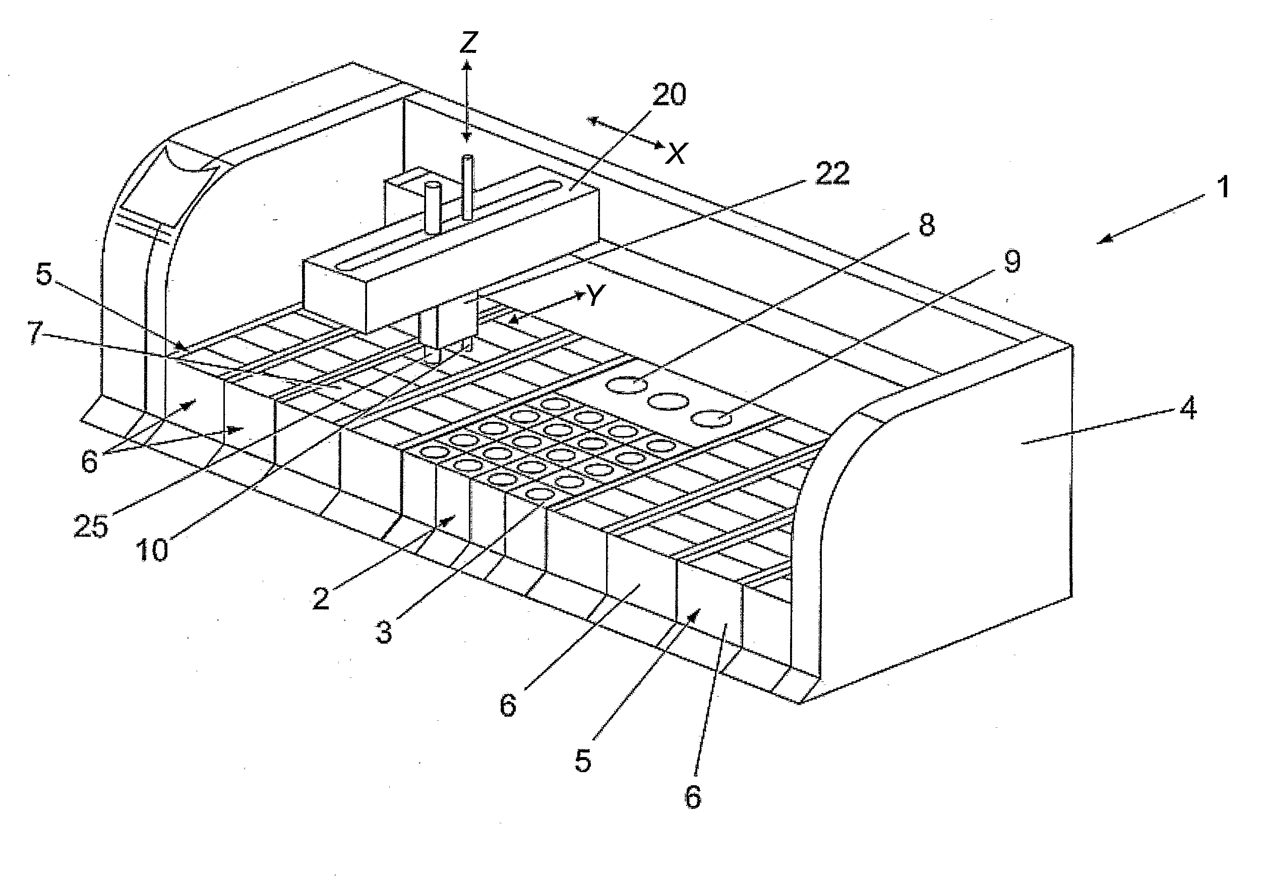
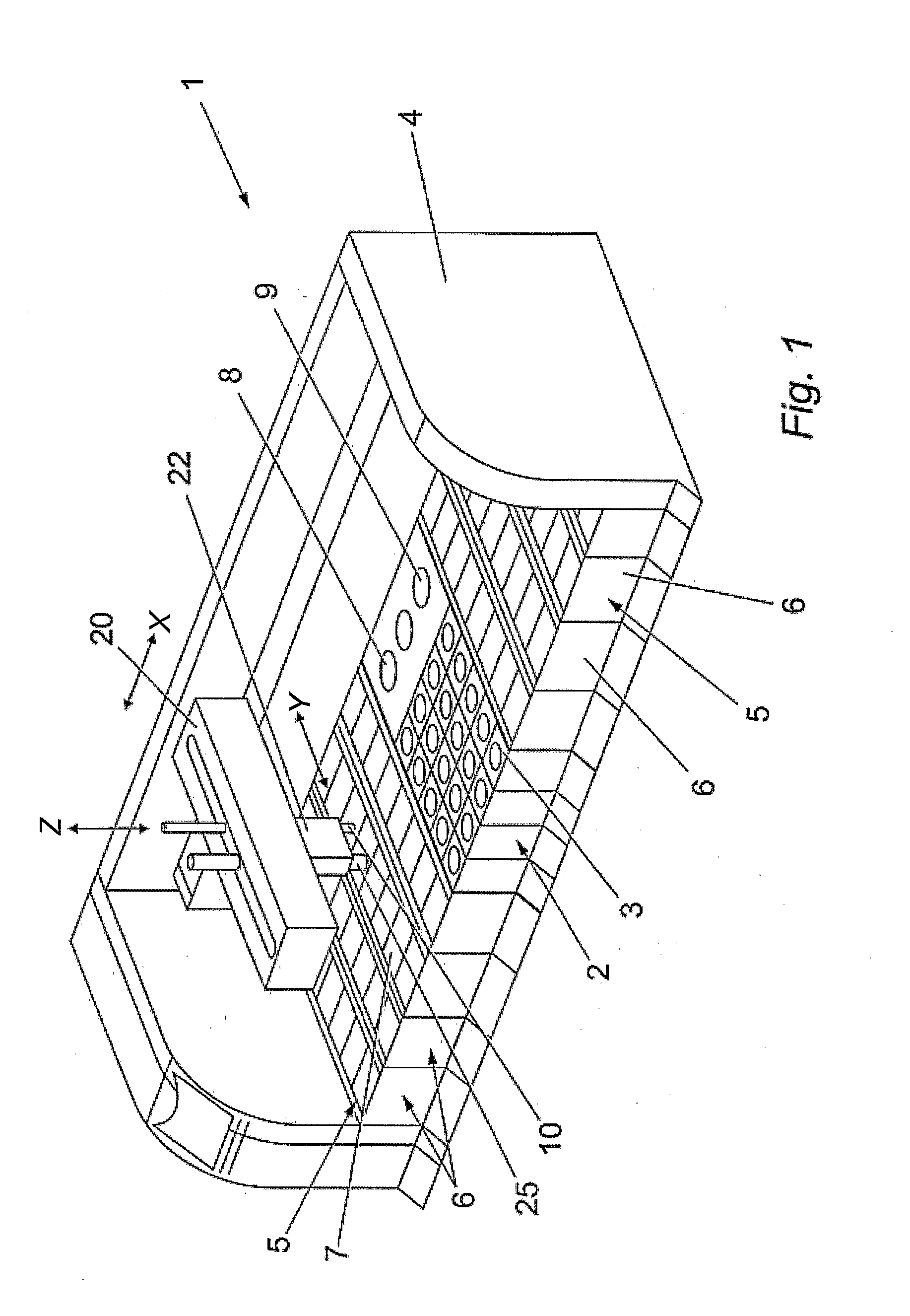
[0107]Whenever needed—and typically when a different reagent is to be aspirated and dispensed—the robot system may move the probe to a washing station 8 that is able to clean the probe 10, thereby removing all traces of the preceding reagent from the probe.

[0108]In a preferred embodiment, the washing station 8 (FIG. 8) comprises deep receptacle 81 able to accommodate a length of the rigid probe member 102 at least corresponding to the length which may have been dipped into the reagent. Through valves (not shown), the tubing end with fitting 106 may be connected to a source of at least one wash solution or cleaning fluid, which will pass through the tubing 101 and finally be ejected from the probe tip into th...


PUM

PropertyMeasurementUnit
internal diameteraaaaaaaaaa
lengthaaaaaaaaaa

Abstract

The invention concerns reagent delivery system for an apparatus for processing of biological samples arranged on microscope slides, comprising a reagent section having one or more reagent containers; a slide section in which at least one microscope slide is arranged; a probe for dispensing a portion of reagent onto a predetermined microscope slide, and means for handling the probe. The probe comprises a continuous prove tubing element extending through a rigid probe member and connecting the probe tip to a pneumatic pressure regulation device. The reagent containers are adapted for cooperation with the probe tip. In this manner a high though-put and a very low carry over of fluid residues is achieved since there is no assembled parts making up the inside volume of the probe in which the fluid may be retained.

Description

TECHNICAL FIELD[0001]The invention relates to a reagent delivery system in an apparatus for processing biological samples arranged on carrier elements, and a staining apparatus for processing biological samples as well as a reagent-dispensing device and a reagent container for use in such delivery systems and apparatus. The invention further relates to a method of aspirating and dispensing reagents[0002]Reagent delivery systems may be used in an automated sample processing apparatus, such as staining apparatus, for treating samples arranged on carrier means, such as microscope slides or sample tubes, located at predefined positions close to or in the apparatus by aspirating a portion of selected reagent from a station containing a plurality of reagents and thereafter dispense the reagent to a sample, e.g. a tissue, organic cells, bacteria etc., arranged on the carrier means. The invention facilitates the aspiration and dispensing of reagents.BACKGROUND ART[0003]Staining apparatuses ...

Claims


Application Information

Patent Timeline
Patent Type & Authority Applications(United States)
IPC IPC(8): G01N1/30B01L3/02B01L3/00G01N1/31G01N35/10
CPCB01L3/508G01N1/312Y10T436/2575G01N35/109G01N1/30G01N35/1002
Inventor FAVUZZI, JOHN A.MARTIN, MERRITT M.SWEDA, JONATHAN R.BLAND, LAURENLATHROP, ROBERT L.VAN BOSCH, JOHN E.BUCHANAN, KRISTOPHER S.
Owner AGILENT TECH INC
Why Eureka
Try Eureka