

Suspended getter material-based structure
a technology of getter material and spherical material, which is applied in the field of getter material-based structure, can solve the problems of power, i.e. the amount of energy and the heating time, and the need, and achieve the effects of low thermal inertia, low energy consumption, and large gas absorption area
- Summary
- Abstract
- Description
- Claims
- Application Information
AI Technical Summary
Benefits of technology
Problems solved by technology
Method used
Image

Examples
first embodiment
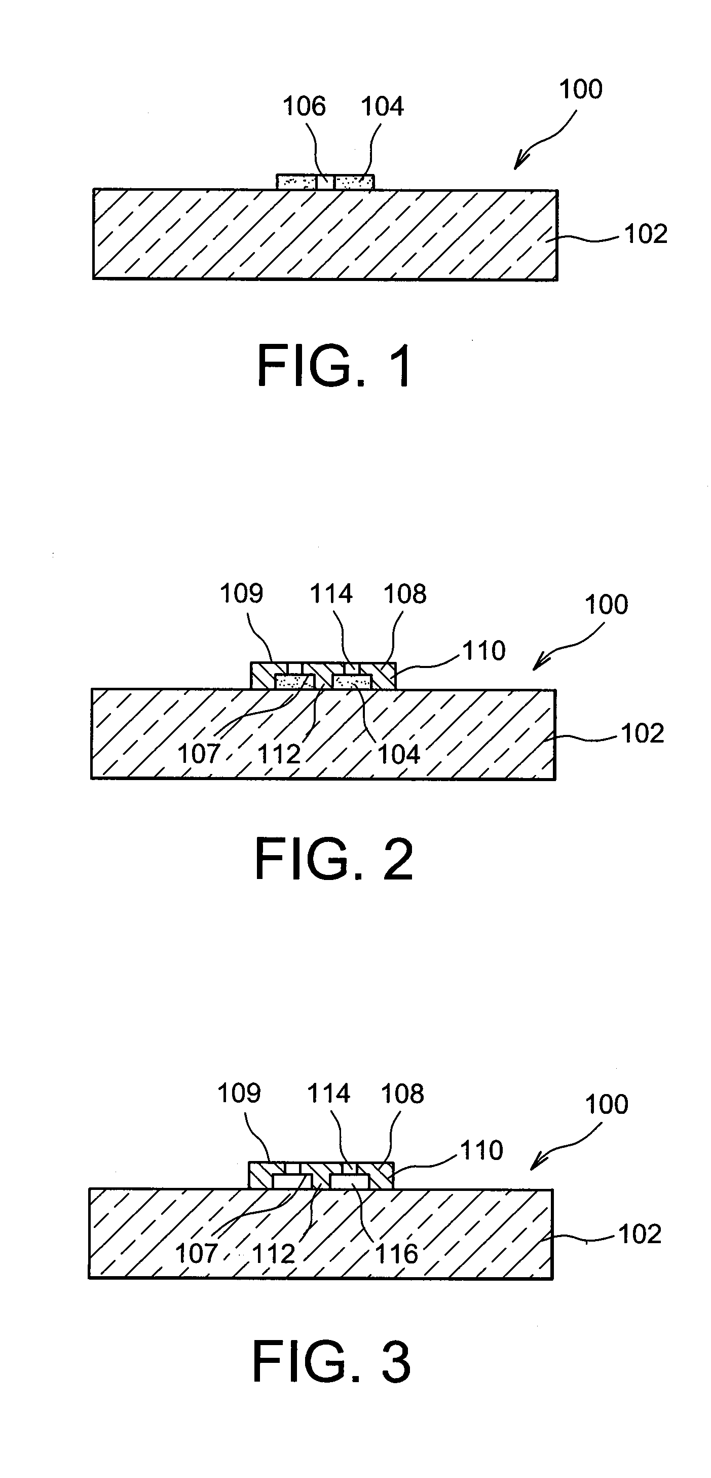
[0076]Reference is first made to FIGS. 1 to 4, which show the steps of a process for producing a getter structure 100 as well as a process for producing a microelectronic system 1000, according to a specific embodiment, comprising the getter structure 100.
[0077]The getter structure 100 is made of a substrate 102, that is for example glass-based. The substrate 102 could also be based on a semiconductor such as silicon, and optionally be covered with an oxide-based layer or any other material capable of achieving thermal insulation of the substrate 102. As shown in FIG. 1, a sacrificial layer 104, for example based on a resin, a polymer such as a photosensitive resin or a metal such as copper or aluminum, is deposited on the substrate 102. Any other sacrificial material can be used to form the sacrificial layer 104, for example an oxide. In general, the sacrificial layer 104 can have a thickness between around 1 μm and 10 μm. The use of resin enables in particular a sacrificial layer...
second embodiment
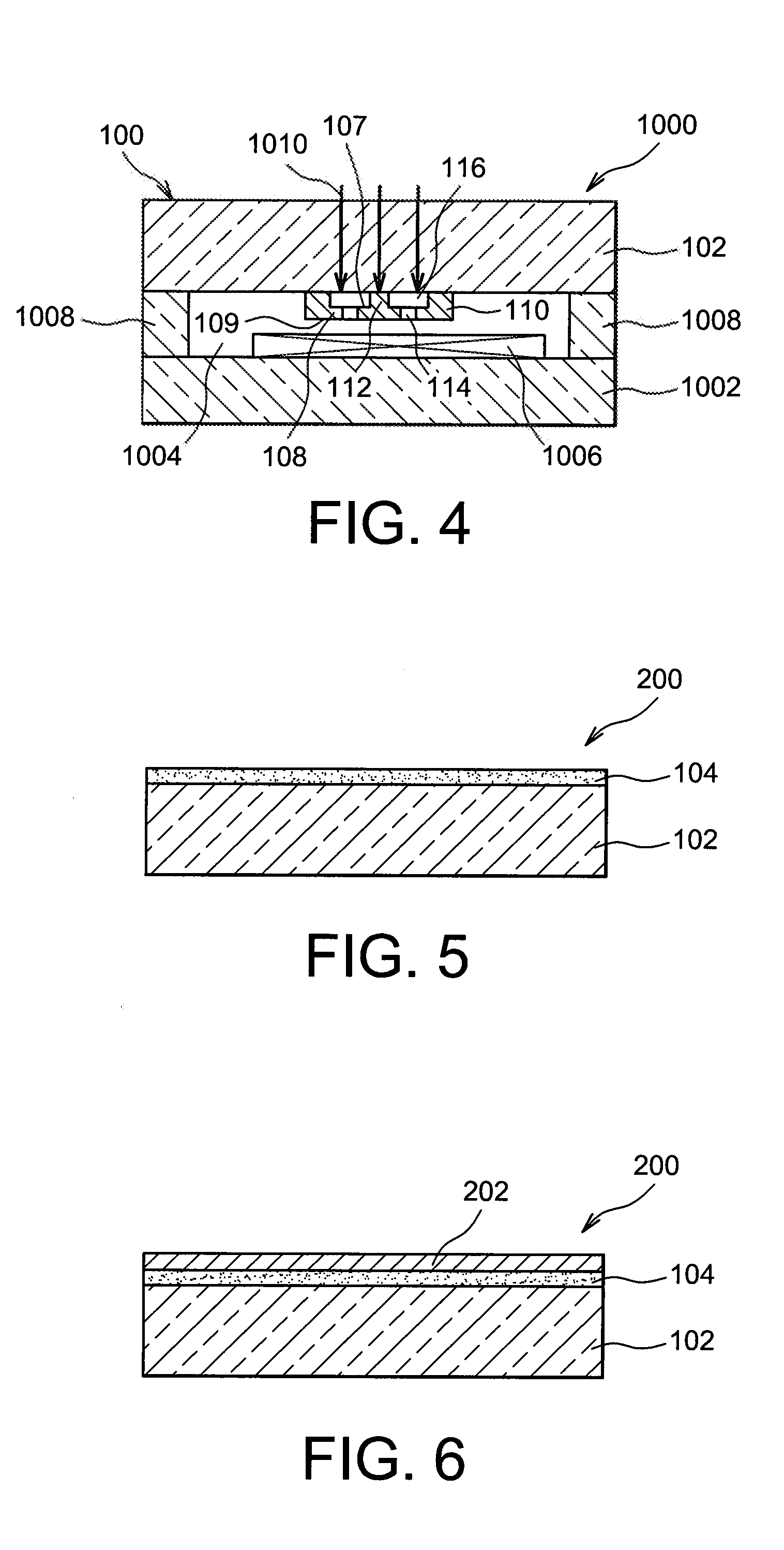
[0095]Reference is now made to FIGS. 5 to 8, which show the steps of a process for producing a getter structure 200 according to a
[0096]As shown in FIG. 5, the getter structure 200 comprises the substrate 102, for example similar to that described in association with the first embodiment, on which the sacrificial layer 104 is formed, also similar to that described above.
[0097]An adhesion layer 202 is then deposited on the sacrificial layer 104 (see FIG. 6). This adhesion layer 202 can be titanium- and / or zirconium- and / or chromium-based. Depending on the material chosen to produce this adhesion layer 202, it can have absorbent properties with respect to gaseous species. The thickness of this adhesion layer 202 can be between around 5 nm and 100 nm.
[0098]As shown in FIG. 7, a getter material is then deposited on the adhesion layer 202, forming a layer 108 for example similar to that described above in association with the first embodiment. This layer 108 is then structured, thus form...
third embodiment
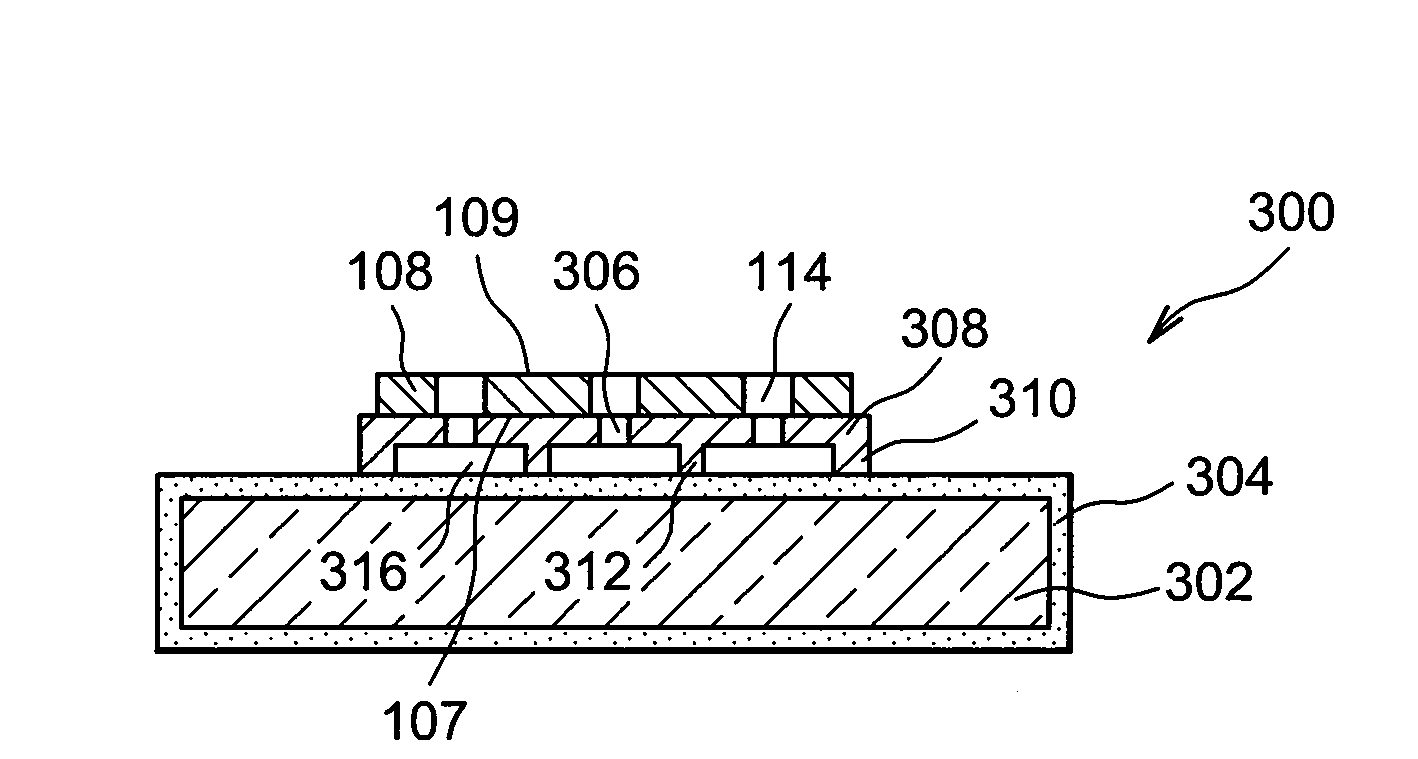
[0103]Reference is made to FIGS. 10 to 13, which show the steps of a process for producing a getter structure 300 according to a
[0104]The getter structure 300 comprises a silicon-based substrate 302, on which a silicon oxide layer 304 is formed, producing a thermal insulation layer around the substrate 302 (FIG. 10). As in the first embodiment, a sacrificial layer 104 is formed on the oxide layer 304 and structured, thus forming openings through this layer 104. A material intended to serve as a heating material, for example tungsten or any other suitable material, is deposited on the sacrificial layer 104, thus forming a layer 308. As shown in FIG. 11, this deposition of heating material is structured according to a “serpentine” pattern, i.e. forming a continuous line with a plurality of bends in the form of a series of safety pins. In an alternative, this pattern could also form a continuous line wound in a spiral. Such a structuring enables the layer 308 to achieve good heat resis...
PUM
| Property | Measurement | Unit |
|---|---|---|
| thickness | aaaaa | aaaaa |
| thickness | aaaaa | aaaaa |
| thickness | aaaaa | aaaaa |
Abstract
Description
Claims
Application Information