Laser light source device and laser irradiation apparatus using the same

a laser irradiation and laser light source technology, applied in the direction of laser details, electrical devices, active medium materials, etc., can solve the problems of high coherence, small laser beam, and likely spatial intensity modulation, and achieve nonlinear coupling through sum frequency generation between modes that is significantly small, prevent or reduce, and reduce the effect of coherency

Active Publication Date: 2010-01-07
SONY CORP
View PDF5 Cites 214 Cited by
  • Summary
  • Abstract
  • Description
  • Claims
  • Application Information

AI Technical Summary

Benefits of technology

[0016]With this configuration, the obtained output light is the transverse-multimode light which is obtained by pumping the laser medium with the transverse-multimode light. The transverse-multimode light has a very low coherency and the spatial intensity modulation hardly occurs due to interference fringes. Also, since the overlap in the transverse multimode is small, the nonlinear coupling through sum frequency generation between modes is significantly small. Hence, it can prevent or reduce that the spatial intensity modulation varies with time and results in a noise of the output. Further, the transverse multimode provides

Problems solved by technology

However, a M2 value of the laser beam is small and coherency is high.
Thus, if a homogenizer equalizes the beam, spatial intensity modulation likely occurs due to interference fringes.
Also, the spatial intensity modulation may vary with time, likely resulting in a noise of the output.
Therefore, the optical path may become long, and the degree of freedom for design may be limited (see “The Review of Laser Engineering”, a publication of The Laser Society of Japan, Vol. 34, No. 10, 693, 2006).
When a silicon thin film is irradiated with the second ha

Method used


Image

  • Laser light source device and laser irradiation apparatus using the same
  • Laser light source device and laser irradiation apparatus using the same
  • Laser light source device and laser irradiation apparatus using the same

Examples


first embodiment

[1] First Embodiment

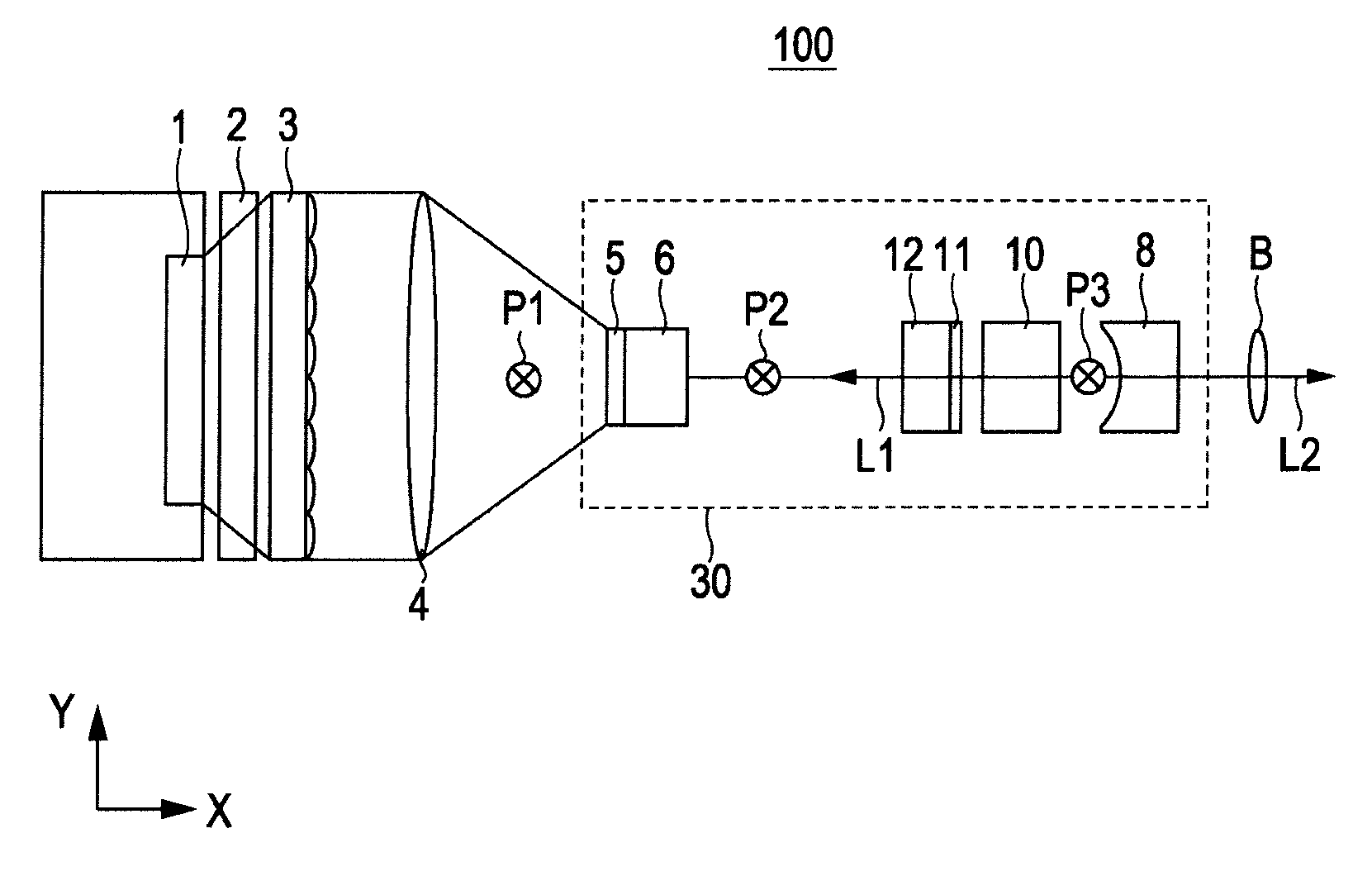
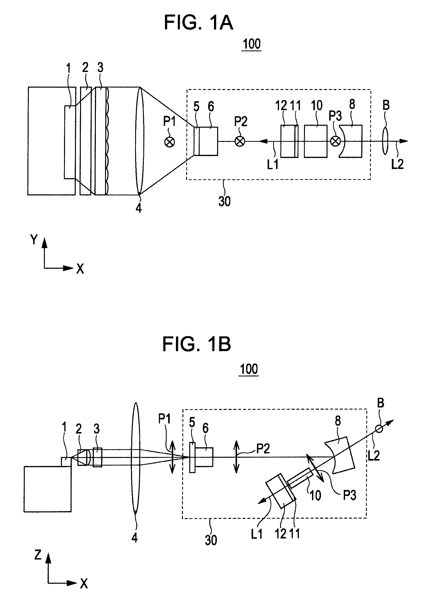
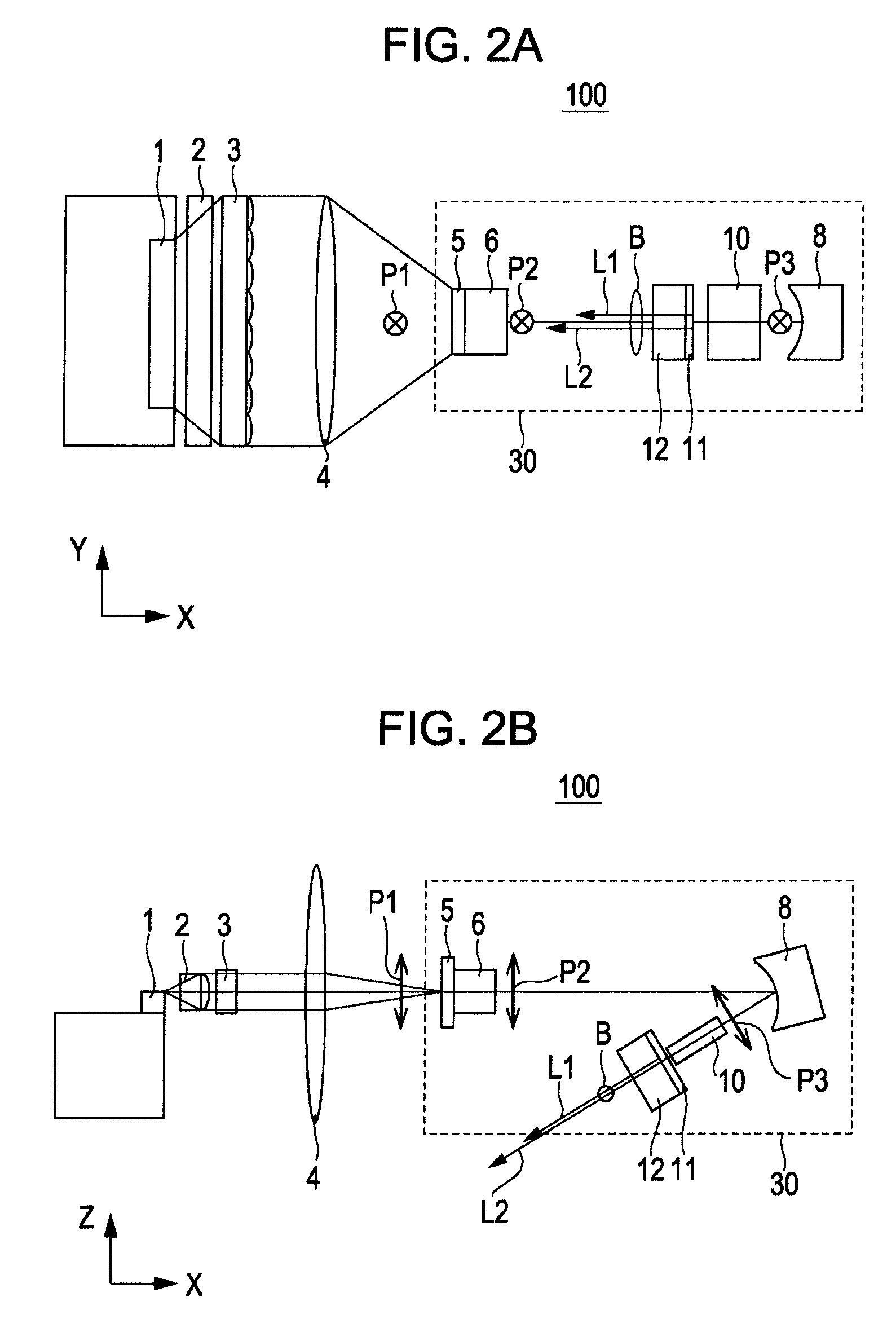
[0034]FIGS. 1A, 1B, 2A, and 2B illustrate brief configurations of laser light source devices according to a first embodiment of the invention. The laser light source device of this embodiment uses linear transverse-multimode light. The longitudinal direction of the light represents the Y direction, the short-axis direction thereof represents the Z direction, and a light-advancing direction represents the X direction. FIGS. 1A and 2A are configuration diagrams taken along the X-Y plane, and FIGS. 1B and 2B are configuration diagrams taken along the X-Z plane.

[0035]Referring to FIGS. 1A, 1B, 2A, and 2B, a laser light source device 100 includes a pump light source 1, such as a laser diode array, which outputs transverse-multimode pump light. Collimator optical systems 2 and 3, and a condenser lens 4 are arranged on an emission optical path of the pump light source 1. A reflecting film 5 serving as a resonator mirror, a laser medium 6, and a reflecting portion 8 for ...

second embodiment

[2] Second Embodiment

[0078]Next, a laser light source device according to a second embodiment of the invention will be described. FIGS. 8A and 8B are configuration diagrams briefly showing the laser light source device according to the second embodiment.

[0079]In this embodiment, a pulse generating mechanism, such as a Q switch element or a saturable absorber, is provided in the laser light source device of the first embodiment. Alternatively, in this embodiment, an application current to the pump light source such as a laser diode is directly modulated. With this configuration, a fundamental wave and a converted wave from the resonator are extracted as pulse oscillation light. In FIGS. 8A and 8B, like numerals refer like components corresponding to FIGS. 1A and 1B, and redundant description is omitted. FIGS. 8A and 8B show an example in which a pulse generating mechanism 20 formed of a Q switch element or a transmissive saturable absorber like Cr:YAG is arranged between the laser me...

third embodiment

[3] Third Embodiment

[0093]Next, examples of a laser irradiation apparatus according to a third embodiment of the invention will be described with reference to FIGS. 12A through 15B. In each example, the laser light source device described in any of the first and second embodiments can be used. The example may be applied to a laser annealing process of amorphous Si or the like for a thin-film transistor (TFT). By performing scanning in the short-axis direction with converted light from the laser light source device or a line laser beam including converted light and fundamental light, a desirable temperature change process like slow cooling process can be provided in the annealing process as described above. That is, by using the laser irradiation apparatus as a laser process apparatus, uniformity of a TFT can be kept and the performance of a TFT can be improved.

[0094]FIGS. 12A to 12D are configuration diagrams briefly showing a laser irradiation apparatus 200 according to this embodi...


PUM


Abstract

A laser light source device includes a pump light source which emits transverse-multimode light; a plurality of resonator mirrors which define a resonator, at least part of the resonator mirrors outputting light to the outside, where the output light having plural wavelengths; a laser medium arranged in the resonator, the laser medium being pumped with the transverse-multimode light emitted from the pump light source; and a wavelength conversion element arranged in the resonator, the wavelength conversion element being irradiated with a transverse-multimode line beam of fundamental wave obtained by oscillation at the laser medium and outputting a line beam of converted wave.

Description

BACKGROUND OF THE INVENTION[0001]1. Field of the Invention[0002]The present invention relates to a laser light source device that outputs transverse-multimode light, and a laser irradiation apparatus using the laser light source device.[0003]2. Description of the Related Art[0004]In recent years, a laser annealing technique has become popular, in which an amorphous silicon thin film is irradiated with laser light to change the amorphous silicon thin film into a polycrystalline silicon thin film. This process is a modification process contained in laser processes such as modifying, processing (punching, cutting, welding, etc.) a substance, or exposing a substance (lithography). The technique is used for a manufacturing process of a thin-film transistor (TFT) which is applied to, for example, a liquid crystal display device or an organic electroluminescence display device. The technique is also used for a manufacturing process of an optical sensor such as a line sensor, a photovoltaic...

Claims


Application Information

Patent Timeline
IPC IPC(8): H01S3/11H01S3/10
CPCH01L21/268H01S3/08059H01S3/08086H01S3/0815H01S2301/20H01S3/094069H01S3/09415H01S3/109H01S3/113H01S3/082
Inventor KIMURA, KAORUOKA, MICHIO
Owner SONY CORP
Why Eureka
Try Eureka