Surface activated biochip

Inactive Publication Date: 2010-01-07
SPIRE
View PDF23 Cites 7 Cited by
  • Summary
  • Abstract
  • Description
  • Claims
  • Application Information

AI Technical Summary

Benefits of technology

[0013]In other aspects, the invention provides a method for identifying the presence of a target molecule (i.e., an analyte) in a test sample. The method includes a step of providing a surface with a plurality of micro-locations formed in discrete regions thereof, where each micro-location has an effective dose of an ion implanted therein such that the location has a differential affinity for a compound vis-à-vis the remainder of the surface. A probe is deposited at each micro-location to generate a plurality of bound probes, each probe itself being capable of binding or otherwise reacting with the analyte. A test sample is then applied to these probes. The combination of the test sample and the probes is incubated under conditions that allow a target molecule, if present, to interact with at least one of the plurality of the probes. A detection signal from each micro-location is monitored such that an alteration in the detection signal at a micro-location indicates the presence of a target macro-molecule at that location, thereby identifying the presence of a target macro-molecule in the test sample. For example, the probes can comprise oligonucleotides having a detectable label, for example, a fluo

Problems solved by technology

One drawback of such methods is that the oligonucleotides or peptides in the microarrays are immobilized in particular configurations, which may inhibit optimal interactions between target sequences in test samples and the immobilized oligonucleotides or peptides.
Further, even in microarrays that utilize three-dimensional gel pads, although the oligonucleotides are not immobilized, the interactions between the oligonucleotides within the gel and the test sample are not optimal because they occur within the

Method used


Image

  • Surface activated biochip
  • Surface activated biochip
  • Surface activated biochip

Examples


Embodiment Construction

[0022]So that the invention may more readily be understood, certain terms are first defined:

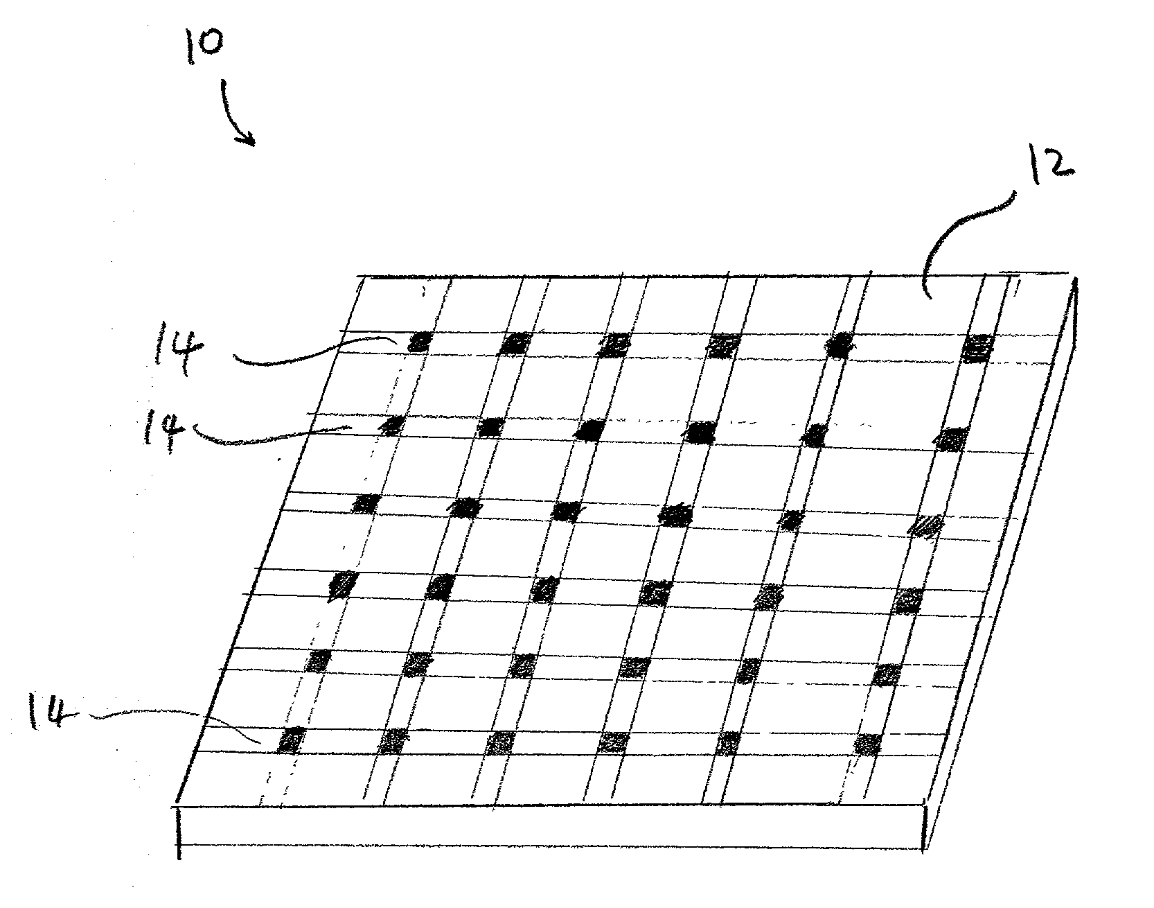
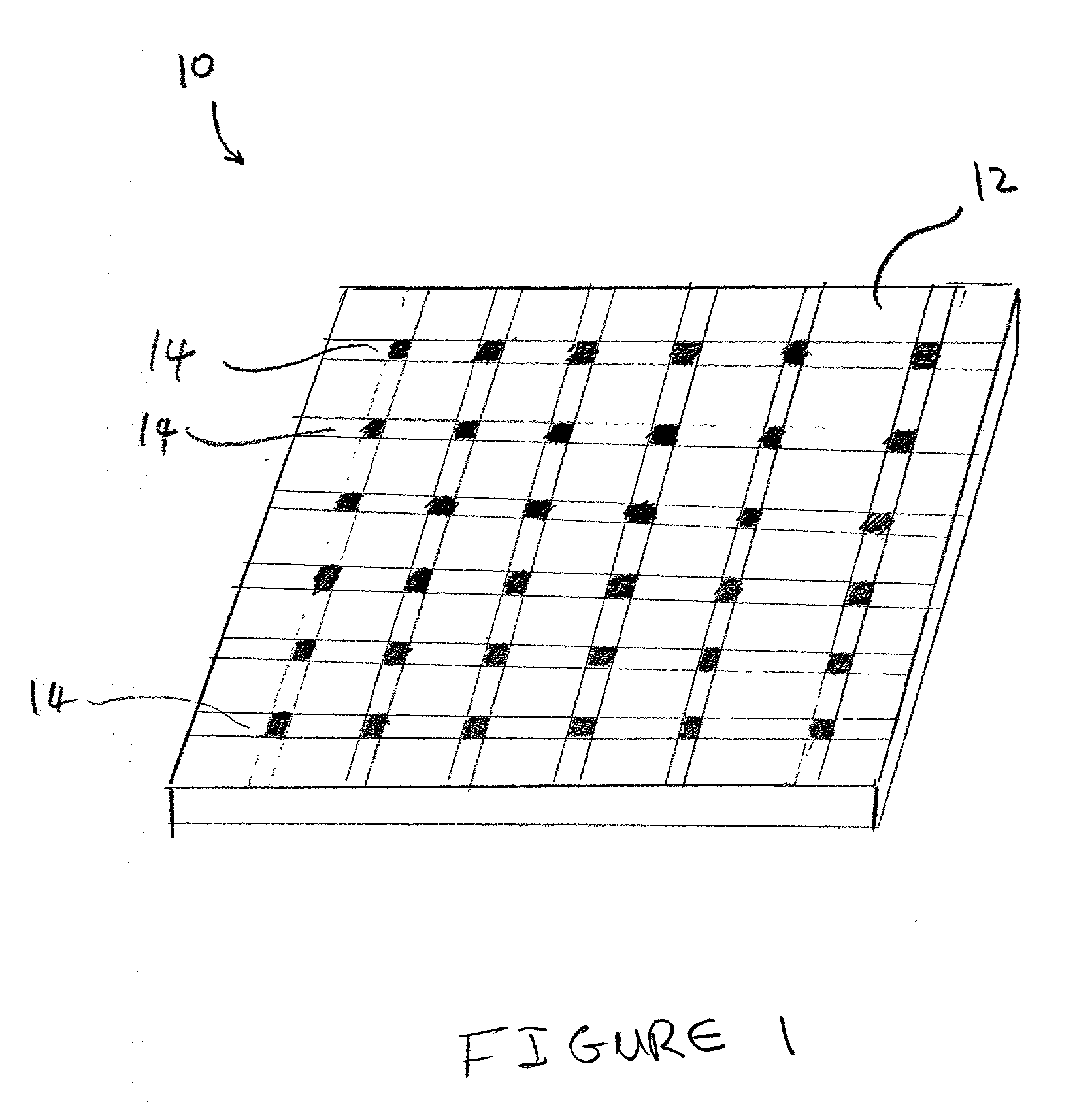
[0023]The term “micro-location”, as used herein, refers to a localized area on a substrate surface in which a dose of an ion has been implanted. A micro-location may have any convenient geometrical shape and / or surface topolography, e.g., circular, rectangular, elliptical, wedge-shaped, conical, and the like. Further, a micro-location may be formed as a flat portion of a substrate surface, or alternatively, it can have a three-dimensional structure e.g., a well, a cavity, or depression, raised regions, etches, trenches, or the like.

[0024]The term “surface”, as used herein refers to any material that is rigid or semi-rigid onto, or into which ions can be implanted or deposited using standard ion implantation techniques. Preferably, the surface is substantially flat, although curved surfaces can also be utilized in the present invention. Examples of suitable surfaces include, but are not limite...


PUM

PropertyMeasurementUnit
Densityaaaaaaaaaa
Semiconductor propertiesaaaaaaaaaa

Abstract

The present invention provides substrates having a plurality of micro-locations on its surface. Each micro-location has an effective dose of an ion beam treatment such that the plurality of the micro-locations exhibit an affinity to a compound that is different from the affinity of the remainder of the substrate surface to that compound. The substrates of the invention can be utilized to form microarrays of biological molecules, such as oligonucleotides or peptides. Such microarrays can find a variety of applications. For example, they can be employed in large scale hybridization assays in many genetic applications, such as mapping of genomes, monitoring of gene expression, DNA sequencing, genetic diagnosis, and genotyping of organisms.

Description

BACKGROUND OF THE INVENTION[0001]The present invention provides substrates on which a microarray of molecules, such as a microarray of oligonucleotides, can be formed, and further provides methods for generating such microarrays.[0002]Microarrays of hundreds or thousands of biological compounds are widely utilized for biological analysis. Tiny droplets, each containing a different known reagent, usually distinct polynucleotide or polypeptide biopolymers, such as, known DNA fragments, can be deposited and immobilized in a regular array on a solid substrate, such as a glass microscope slide. The array of reagents can be exposed to an analyte solution containing unknown target sequences, for example, complementary DNA (cDNA) fragments, pre-labeled with fluorescent or radioactive chemical labels. Under certain conditions, binding reactions or hybridizations occur between a polynucleotide sequence in the array and a complementary sequence in the analyte. Subsequent optical or radiosensit...

Claims


Application Information

Patent Timeline
IPC IPC(8): C40B40/08C40B40/10C40B40/06B01J19/00C40B60/14
CPCB01J19/0046C40B60/14B01J2219/00529B01J2219/00531B01J2219/00576B01J2219/00596B01J2219/00605B01J2219/00608B01J2219/0061B01J2219/00612B01J2219/00619B01J2219/00621B01J2219/00632B01J2219/00637B01J2219/00659B01J2219/00677B01J2219/00722B82Y30/00C40B40/06B01J2219/00445
Inventor LITTLE, ROGER G.
Owner SPIRE
Why Eureka
Try Eureka