

Prosthetic Valve for Transluminal Delivery
a technology of prosthetic valves and deployment systems, applied in the field of prosthetic cardiac valves and related deployment systems, can solve the problems of complex complexes, complicated recovery, and prolonged patient hospitalization, and achieve the effects of avoiding substantial migration of the prosthetic valve assembly, eliminating problems, and optimizing function and durability
- Summary
- Abstract
- Description
- Claims
- Application Information
AI Technical Summary
Benefits of technology
Problems solved by technology
Method used
Image

Examples
Embodiment Construction
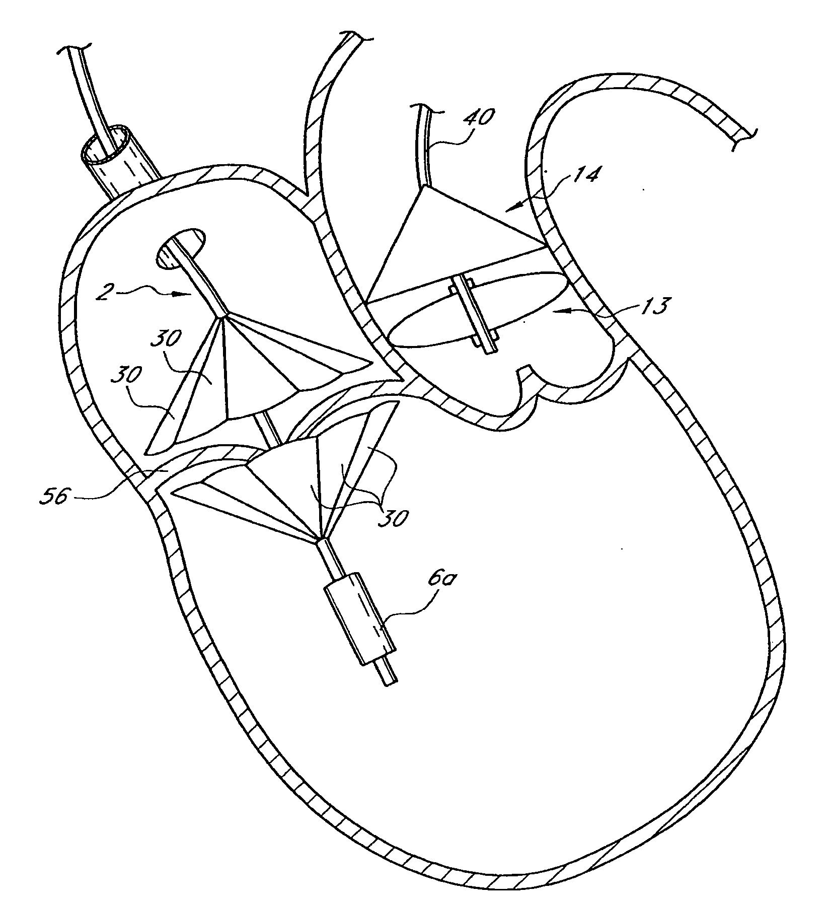
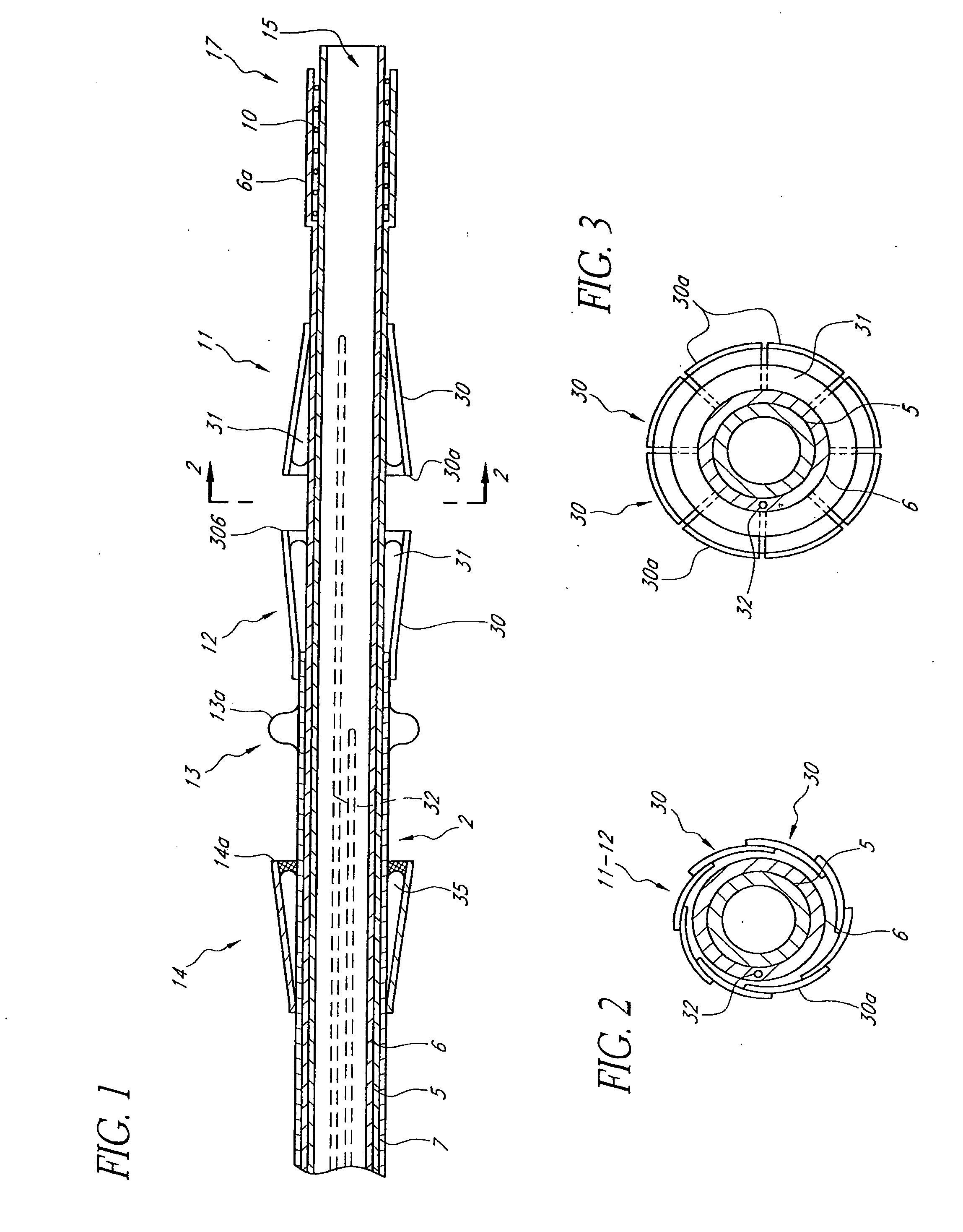
[0106]Reference is now made to the figures wherein like parts are designated with like numerals throughout. FIGS. 1 to 3 represent a device 1 for replacing a heart valve by a percutaneous route. This device comprises a tubular catheter 2 formed from three tubes 5, 6, 7 engaged one inside the other and on which there are placed, from the proximal end to the distal end (considered with respect to the flow of blood, that is to say from right to left in FIG. 1), a prosthetic valve 10, two series of blades 11, 12, a balloon 13 and a filter 14. The three tubes 5, 6, 7 are mounted so that they can slide one inside the other. The interior tube 5 delimits a passage 15, the cross section of which is large enough to allow blood to flow through it. At the proximal end, the intermediate tube 6 forms a bell housing 6a delimiting, with the interior tube 5, an annular cavity 17 in which the prosthetic valve 10 is contained in the furled condition.
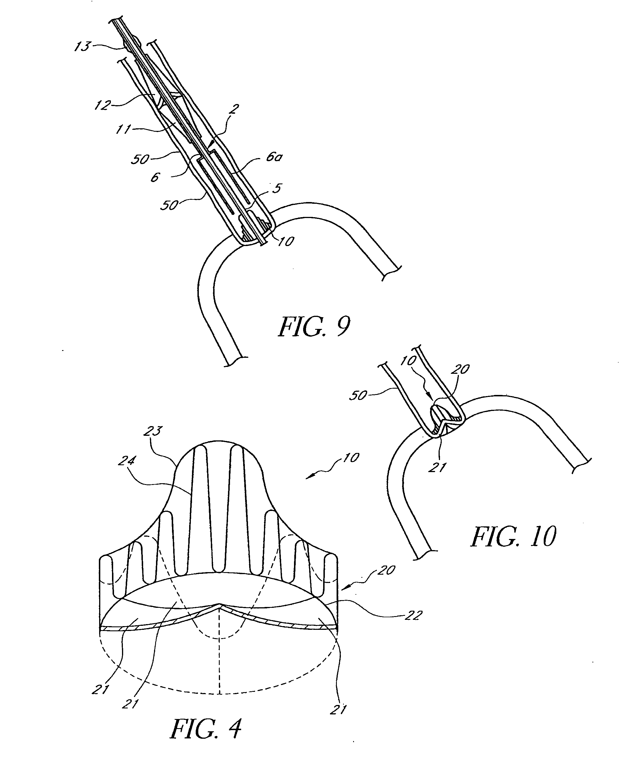
[0107]FIG. 4 shows that this valve 10 comprises an a...
PUM
 Abstract
Description
Claims
Application Information