
Plasma processing method and plasma processing apparatus

a plasma processing and plasma technology, applied in the field of plasma processing apparatuses, can solve the problems of low high insufficient disclosure of art for maintaining a constant inner temperature of the plasma processing chamber, etc., to achieve high plasma processing accuracy, rapid heating, and constant plasma processing properties

Inactive Publication Date: 2010-01-07
HITACHI HIGH-TECH CORP
View PDF3 Cites 3 Cited by
  • Summary
  • Abstract
  • Description
  • Claims
  • Application Information

AI Technical Summary

Benefits of technology

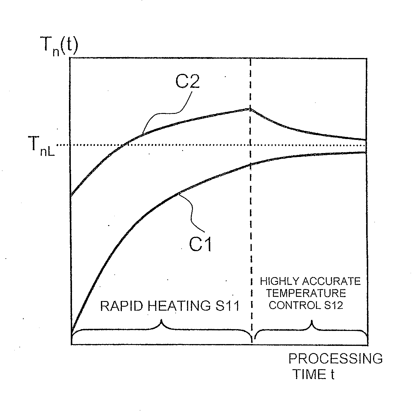
The present invention provides a plasma processing apparatus and method that can accurately control the temperature of the plasma processing chamber using plasma, resulting in a constant plasma processing property and highly accurate plasma processing. This is achieved through a heating step composed of two or more steps, including a rapid heating step and a high accuracy control step. The invention also includes a computing machine for computing the optimum plasma heating condition based on the plasma generating condition and the inner temperature of the plasma processing chamber. Overall, the invention allows for precise and consistent plasma processing.

Problems solved by technology

However, the disclosed art is not sufficient for maintaining a constant inner temperature of the plasma processing chamber.
The reason for this is because there are areas in the interior of the processing chamber that cannot be provided with temperature control mechanisms, or are as that cannot be subjected to temperature control since the thermal conductance with respect to the temperature control mechanisms is not good.
However, when the apparatus is used continuously, the temperature of the plasma processing chamber becomes high, and when an apparatus having been stopped for a while is reused, the temperature of the plasma processing chamber is low.
In order to perform rapid heating, a plasma generating condition capable of applying a high energy to the inner walls of the plasma processing chamber via plasma must be set, but since the heating progresses rapidly, temperature control becomes difficult.
According to experiments conducted by the present inventors, in an extreme case, a change as little as a few degrees of temperature of the plasma processing chamber may cause defects.
However, the prior art does not describe the method for realizing such accurate temperature control.
However, since the target object cannot be subjected to plasma processing during such temperature control, the production efficiency is deteriorated, so such art cannot be applied to mass production facilities.

Method used


Image

  • Plasma processing method and plasma processing apparatus
  • Plasma processing method and plasma processing apparatus
  • Plasma processing method and plasma processing apparatus

Examples


embodiment 2

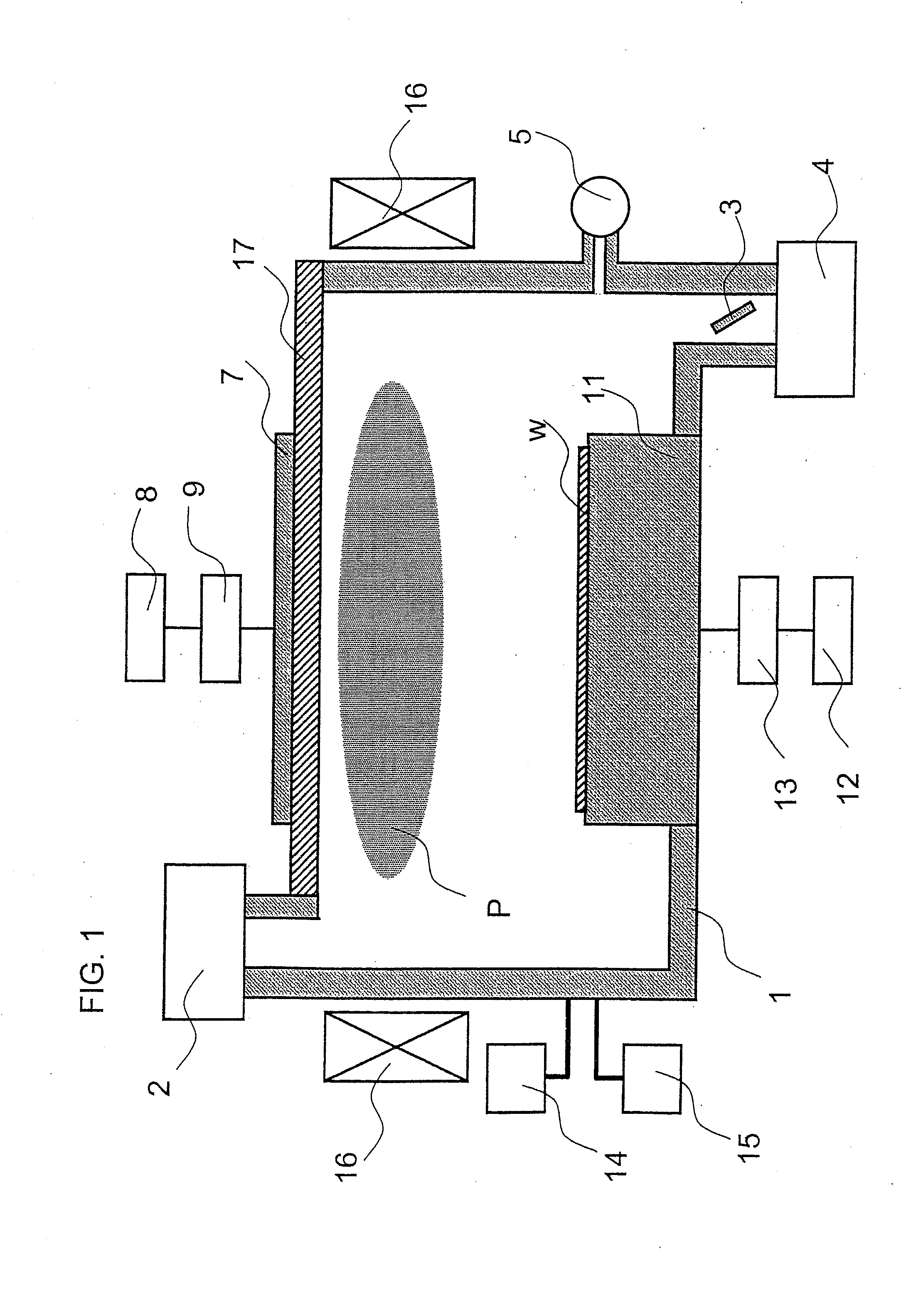
[0038]Therefore, with reference to FIG. 6, the second embodiment of the present invention will be described, in which a temperature computing machine is attached to a general plasma processing apparatus described in the first embodiment, wherein the optimum plasma generating condition is computed through the computing machine. FIG. 6 illustrates a plasma etching apparatus illustrated in FIG. 1 further equipped with a computing machine 21 having an operation unit 24, a display unit 22, a data input means 24, a database 25 and a model storage unit 26. The apparatus also includes a process monitor 31 and a process data logger 32, but the detailed methods for using the same are described later.

[0039]The method for using the computing machine 21 will now be described. At first, prior to shipping the plasma processing apparatus, temperature measuring devices are attached to each points on the interior of the plasma processing chamber 1, on the top panel 17, and on the upper and side surfa...

embodiment 3

[0071]The second embodiment described a method for setting the target temperature so as to discover the temperature to be achieved via the lot pretreatment S1 in order to enhance the reproducibility of the plasma processing S2. However, the level of accuracy for achieving the target temperature required to realize the effect is not clear according to embodiment 2. Therefore, the method for computing the required accuracy level will be described hereafter as embodiment 3.

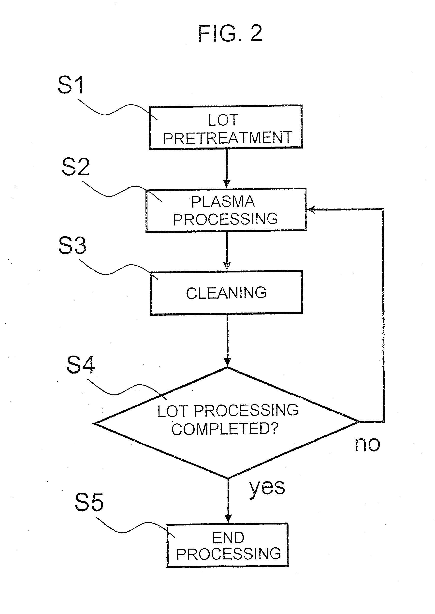
[0072]In embodiment 3, an acceptable temperature fluctuation is computed by correlating the relationship between the result of plasma processing S2 in FIG. 2 and the temperature observed during the cleaning S3 immediately prior to the plasma processing.

[0073]As an example, it is assumed that the transistor gate dimension formed on the semiconductor wafer via the plasma processing S2 is measured. It is assumed that the gate dimension at the y-th processing is Gy, and during the cleaning S3 performed immediately prior ...


PUM

PropertyMeasurementUnit
temperatureaaaaaaaaaa
chemical reactivityaaaaaaaaaa
processing accuracyaaaaaaaaaa

Abstract

The invention provides a plasma processing apparatus capable of setting the temperature of the plasma processing chamber accurately to a specific state, and to perform highly accurate plasma processing while maintaining a constant plasma processing property. The plasma processing apparatus for subjecting a sample w to be processed to plasma processing within a plasma processing chamber 1 comprises a database 25 for correlating and storing the inner temperature of the plasma processing chamber 1 and the plasma generating condition, a model expression storage unit 26 for storing the correlating equation of the inner temperature of the plasma processing chamber 1 and the plasma generating condition from the database 25, and a computing machine 21 having an operation unit 24 for creating the correlation equation and the optimum plasma generating condition, further having a process monitor 31 for monitoring the condition of plasma processing, wherein the value output by the process monitor and the temperature of the plasma processing chamber are correlated and stored in the database 25, and the computing machine 21 computes a plasma processing condition capable of realizing a substantially constant plasma processing chamber temperature, based on which the plasma processing chamber performs plasma processing.

Description

[0001]The present application is based on and claims priority of Japanese patent application No. 2008-174428 filed on Jul. 3, 2008, the entire contents of which are hereby incorporated by reference.BACKGROUND OF THE INVENTION[0002]1. Field of the Invention[0003]The present invention relates to plasma processing apparatuses, especially capable of realizing highly accurate plasma processing in the process of manufacturing semiconductor devices.[0004]2. Description of the Related Art[0005]Plasma processing is used for example to process or modify the surface of the object to be processed by enhancing the chemical reactivity by degrading processing gas via plasma. For example, in a semiconductor manufacturing line, plasma processing is used to deposit thin films on the surface of semiconductor wafers or to perform etching thereof to obtain the desired processing results.[0006]Chemical reaction generally depends on the temperature of the processing chamber, and the above-mentioned plasma...

Claims


Application Information

Patent Timeline
Patent Type & Authority Applications(United States)
IPC IPC(8): G05D23/00G06F17/10
CPCH01J37/32935H01L21/67248H01J37/3299
Inventor IWAKOSHI, TAKEHISASAITO, GO
Owner HITACHI HIGH-TECH CORP
Learn More