Highly sensitive spectroscopic unit

Active Publication Date: 2010-01-14
CARL ZEISS MICROSCOPY GMBH
View PDF0 Cites 8 Cited by
  • Summary
  • Abstract
  • Description
  • Claims
  • Application Information

AI Technical Summary

Benefits of technology

[0009]It is the object of the invention to significantly increase the diffraction efficiency of a spectrum analysis unit with a grating in an economical manner.
[0011]In the solution according to the invention, the light bundle to be spectrally analyzed is predispersed in spectra by a first element and is then split into the spectrum to be detected by another, second element which is optimally adapted to the predispersion. In this connection, it is important that the first element is selected in such a way that it has a very high transmission for the spectrum to be detected. However, the second element can also be a surface grating with a profile shape which remains constant, varies partially, or changes constantly over the surface. In order to obtain a high transmission of the first element influencing the spectrum, a prism or—in another construction—dichroic mirrors are used. The components can be antireflection-coated to reduce Fresnel losses.
[0013]The grating preferably comprises three grating regions, each of whose blaze wavelength is optimally adapted to the respective spectral partial region. The entire grating has a uniform spatial frequency, and the grating grooves of all of the partial regions are aligned exactly parallel to one another. The grating grooves lie in a plane and the dispersion plane extends perpendicularly from the plane. A high diffraction efficiency can be generated in the spectral partial regions in this way. The dispersed light is guided through camera optics (mirror system / lens system) to a detector with an evaluating unit.

Problems solved by technology

The reason for the spectral fluctuation in diffraction efficiency is that the electromagnetic behavior of the grating diffracts a more or less large proportion of the light in diffraction orders other than the desired, first diffraction order, and this light is accordingly lost and even causes scatter light problems.

Method used


Image

  • Highly sensitive spectroscopic unit
  • Highly sensitive spectroscopic unit
  • Highly sensitive spectroscopic unit

Examples


Embodiment Construction

[0028]It is to be understood that the figures and descriptions of the present invention have been simplified to illustrate elements that are relevant for a clear understanding of the present invention, while eliminating, for purposes of clarity, many other elements which are conventional in this art. Those of ordinary skill in the art will recognize that other elements are desirable for implementing the present invention. However, because such elements are well known in the art, and because they do not facilitate a better understanding of the present invention, a discussion of such elements is not provided herein.

[0029]The present invention will now be described in detail on the basis of exemplary embodiments.

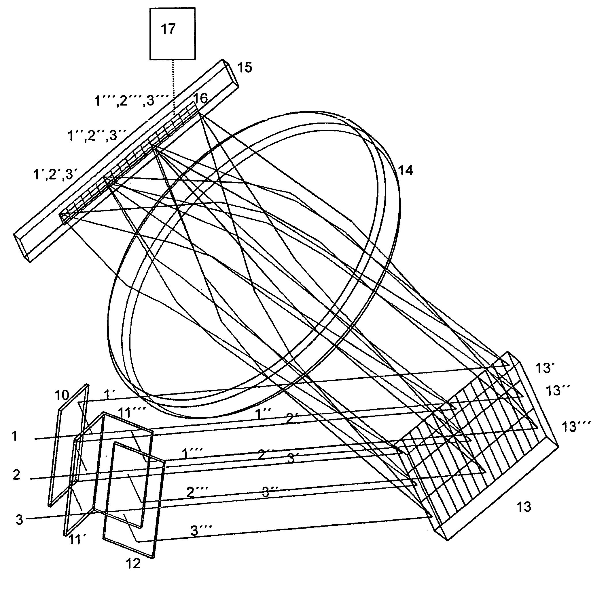
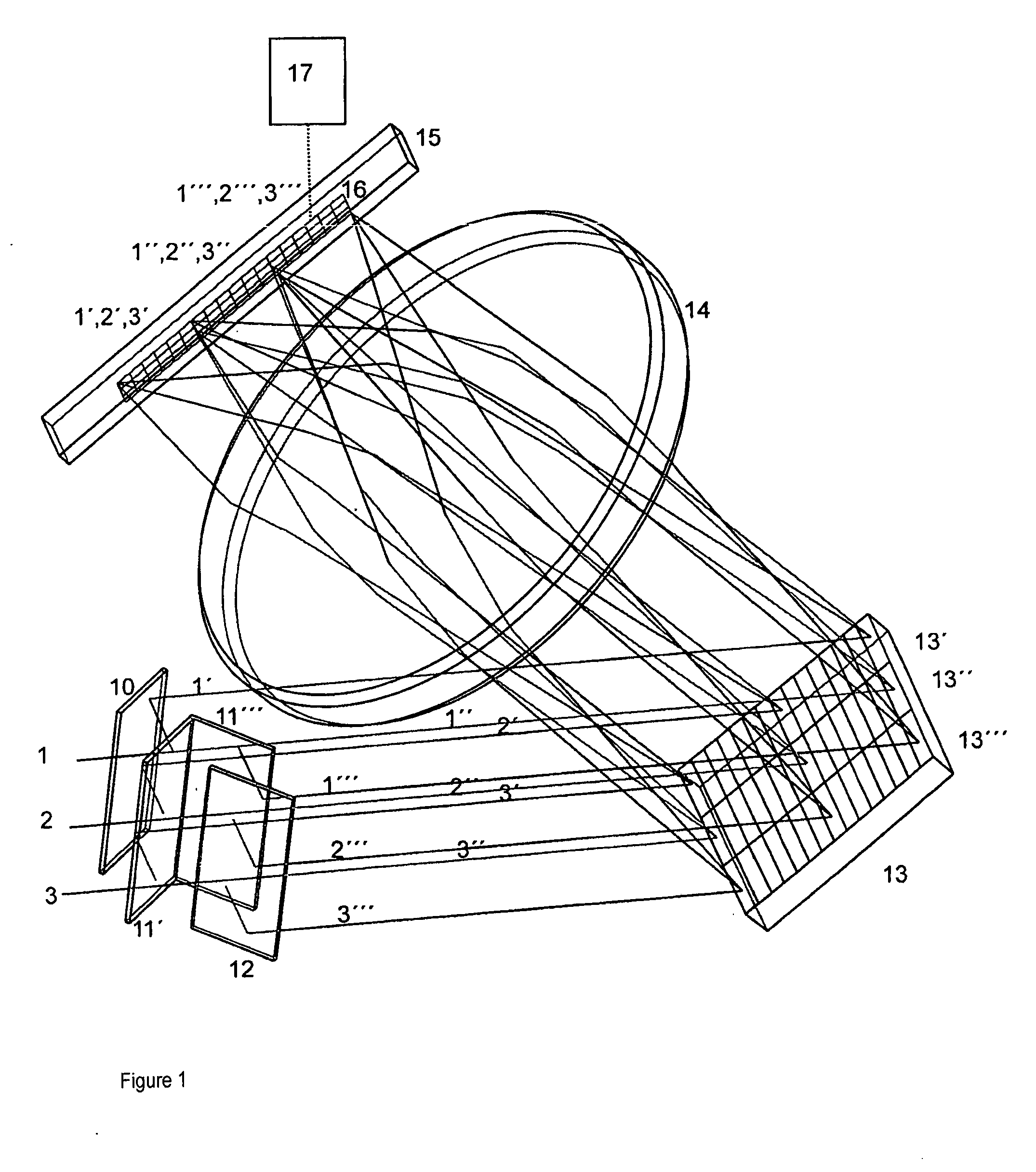
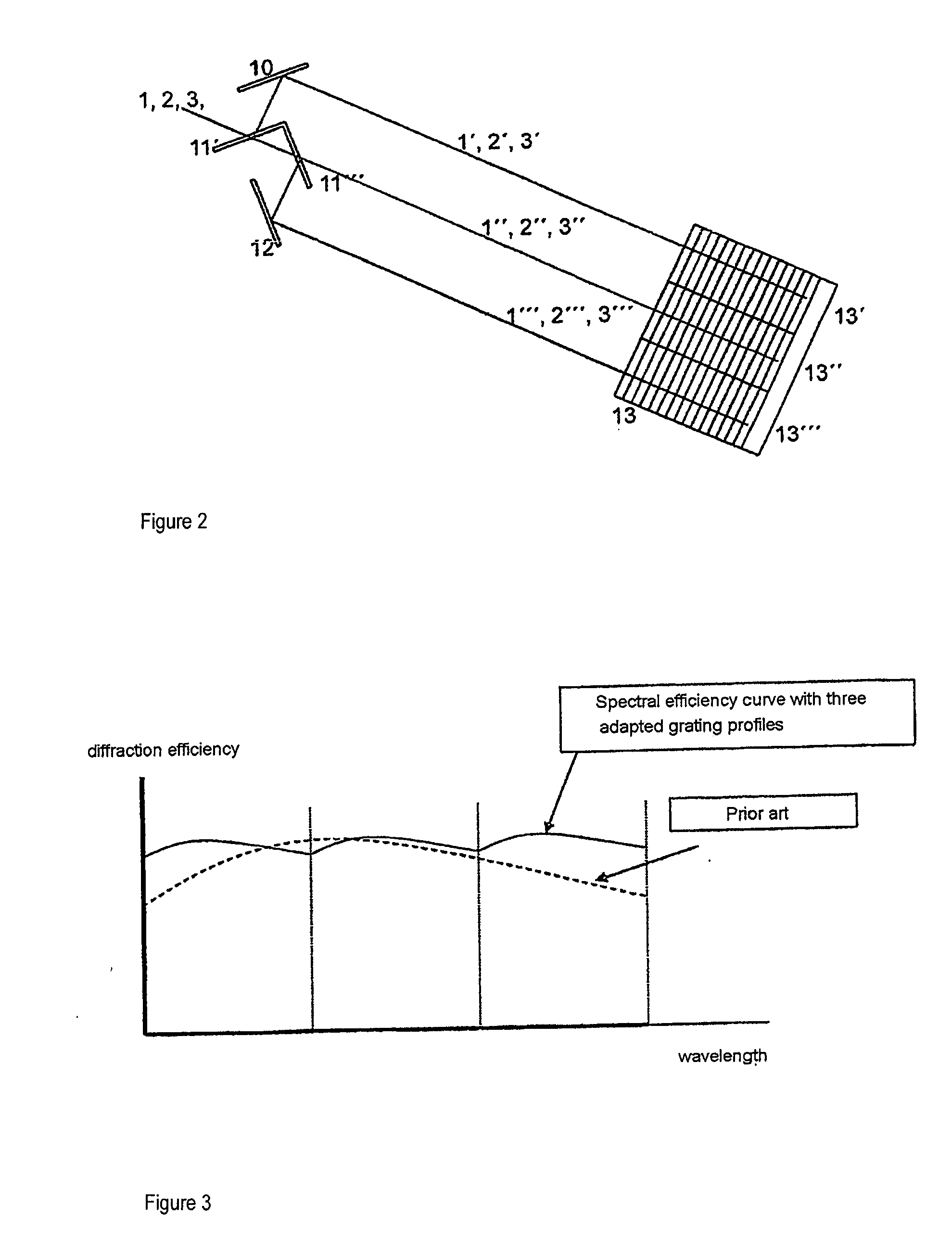
[0030]FIG. 1 shows a first embodiment form of the invention in which dichroic splitters 11′ and 11′″ with highly reflective mirrors 10 and 12 are used for the spectral predispersion. Further, viewed in the light propagation direction, a diffraction grating 13, imaging optics 14...


PUM


Abstract

The invention is directed to a highly sensitive spectrum analysis unit with a diffraction grating, wherein a parallel light bundle having a wavelength range impinges on a diffraction grating which splits the different wavelengths into spectra by diffraction in first directions, and wavelength partial ranges of the spectrally split light bundle can be focused on a detector row by means of camera optics, and evaluation electronics are connected to the detector row and acquire the generated spectrum as information and display it. The invention is characterized in that the light bundle passes a first optical element, and then wavelength partial ranges of a spectrally split light bundle impinge on respective partial regions of a diffraction grating, the diffraction grating having the same grating constant across all partial regions and a changing profile shape, the profile shapes generating different blaze wavelengths that lie in the respective wavelength partial ranges.

Description

[0001]The present application claims priority from PCT Patent Application No. PCT / EP2007 / 008552 filed on Oct. 2, 2007, which claims priority from German Patent Application No. DE 10 2006 047 913.0 filed on Oct. 6, 2006, the disclosure of which is incorporated herein by reference in its entirety.BACKGROUND OF THE INVENTION[0002]1. Field of the Invention[0003]The invention is directed to a highly sensitive spectrum analysis unit which uses a diffraction grating, wherein a parallel light bundle having a wavelength range impinges on a diffraction grating which splits the different wavelengths in spectra by diffraction in first directions. The wavelength partial ranges of the spectrally split light bundle are focused onto a detector row through optics, and evaluating electronics connected to the detector row obtain the generated spectrum as information and display it.[0004]The spectral unit can be applied in all spectrometers. The unit is used in particular in a confocal laser scanning m...

Claims


Application Information

Patent Timeline
IPC IPC(8): G01J3/18G01J3/36G01J3/28
CPCG01J3/02G01J3/021G01J3/0291G01J3/2803G01J3/1804G01J3/26G01J3/14
Inventor WOLLESCHENSKY, RALFDOBSCHAL, HANS-JUERGENSTEINER, REINHARD
Owner CARL ZEISS MICROSCOPY GMBH
Why Eureka
Try Eureka