Dye Doped Graphite Graphene Solar Cell on Aluminum

a solar cell and graphene technology, applied in the field of dye-dyesensitized or dye-doped solar cells, can solve the problems of electrolyte in the form of an electrolytic solution, reproducibility and safety, performance degradation,

Inactive Publication Date: 2010-01-21
CURTIN LAWRENCE +1
View PDF8 Cites 12 Cited by
  • Summary
  • Abstract
  • Description
  • Claims
  • Application Information

AI Technical Summary

Benefits of technology

[0023]In accordance with another embodiment of the present invention, a dye doped solar cell comprising a substrate comprising aluminum; a first layer applied to the substrate, wherein the first layer comprises a material selected from the group consisting of graphite, graphene, C60, carbon nanotubes, and combinations thereof and is doped with boron thereby providing holes or vacancies within the first layer; an intrinsic undoped second layer applied to the first layer, wherein the second layer comprises a material selected from the group consisting of graphite, graphene, C60, carbon nanotubes, and combinations thereof; a doped third layer applied to the second layer, where

Problems solved by technology

As a result, there have been problems in terms of reproducibility and safety due to the leakage of the electrolyte that may be caused when the solar cell is inclined, for example.
When the electrolyte is used in the form of such an electrolytic solution, the solar cell may suffer from, during a long-term service, alteration of solvent molecules, decomposition of solvent molecules, vaporization of low-boiling-point solvent, leakage of electrolytic solution (solvent and/or electrolyte) from sealed parts, etc. with the result that the performance, such as photovoltaic transduction efficiency, thereof is deteriorated.
That is, the use of the electrolyte in the form of an electrolytic solution has a drawback in that the long-term stability is poor.
Moreover, depending on the type of electrolyte used in the electrolytic solution, hygroscopicity is exhibited to thereby absorb water, and it may occur that the water causes the electrolyte and the photosensitizer to decompose to result in performance deterioration.
Furthermore, the surface irreg

Method used


Image

  • Dye Doped Graphite Graphene Solar Cell on Aluminum
  • Dye Doped Graphite Graphene Solar Cell on Aluminum
  • Dye Doped Graphite Graphene Solar Cell on Aluminum

Examples


Embodiment Construction

[0028]Although the following detailed description contains many specifics for the purposes of illustration, anyone of ordinary skill in the art will appreciate that many variations and alterations to the following details are within the scope of the invention. Accordingly, the following preferred embodiments of the invention are set forth without any loss of generality to, and without imposing limitations upon, the claimed invention.

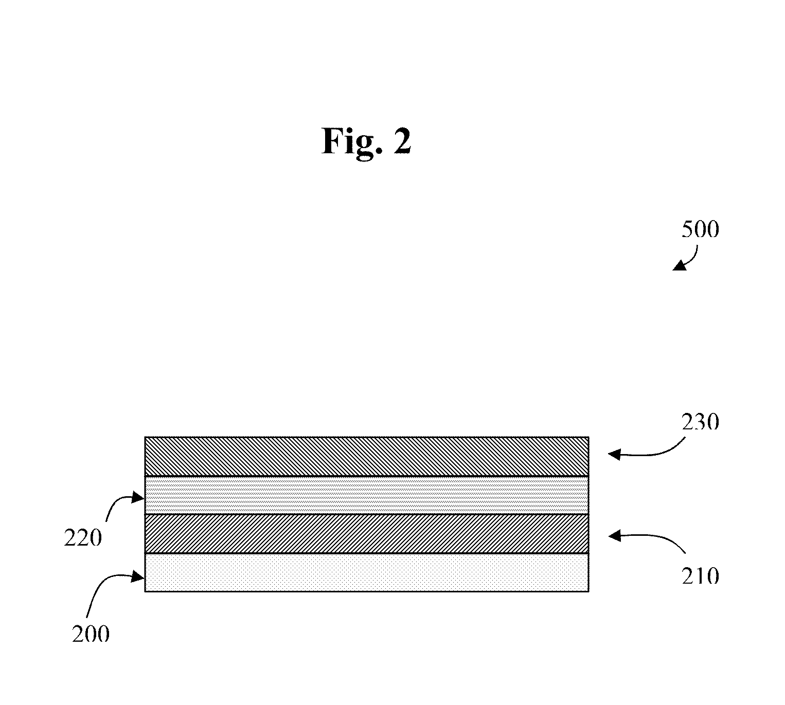
[0029]A preferred embodiment of the layering configuration of solar cell layers 500 of the present invention is illustrated in FIG. 2. The substrate 200 may comprise aluminum that may be provided in the form of aluminum foil, an aluminum sheet, or the like. The substrate 200 need not be limited to only such embodiments of material but may comprise any additional substrate materials known to one of ordinary skill in the art.

[0030]A first layer 210 applied to the substrate 200 may comprise graphite, graphene, C60, carbon nanotubes, or any combinations ther...


PUM


Abstract

An efficient dye doped solar cell that improves upon the conventional dye-sensitized solar cells known within the art. The present inventive dye doped solar cell and its method of manufacture completely eliminate an electrolyte component common to conventional solar cells thereby removing numerous complications found in conventional dye doped cells such as inconsistent reproducibility and safety issues due to leakage of the electrolyte component. The dye doped solar cell of the present invention provides a novel replacement for the conventional electrolyte layer that provides significant improvements in both the safety and function of the inventive dye doped solar cell while eliminating the troublesome electrolyte component that is required in the conventional dye-sensitized doped solar cells known within the art.

Description

CROSS REFERENCE TO RELATED APPLICATIONS[0001]This application claims the benefit of provisional patent application Ser. No. 61 / 080,775, filed with the USPTO on Jul. 15, 2008, which is herein incorporated by reference in its entirety.STATEMENT REGARDING FEDERALLY SPONSORED RESEARCH OR DEVELOPMENT[0002]Not applicable.INCORPORATION-BY-REFERENCE OF MATERIAL SUBMITTED ON A COMPACT DISK[0003]Not applicable.BACKGROUND OF THE INVENTION[0004]1. Field of the Invention[0005]The present invention relates to a dye-sensitized or dye doped solar cell in which light energy is directly converted into electric energy, and a method for manufacturing such dye-sensitized or dye doped solar cells.[0006]2. Background Art[0007]When a photovoltaic material is irradiated with light, electrons restricted to an atom in the photovoltaic material are released by light energy to move freely, which generates free electrons and holes. The free electrons and the holes are efficiently separated so that electric energ...

Claims


Application Information

Patent Timeline
IPC IPC(8): H01L31/00H01L31/18
CPCB82Y10/00Y02E10/547H01L31/0352H01L31/036H01L31/0384H01L31/075H01L51/0045H01L51/0046H01L51/0077H01L51/0093H01L51/4213H01L51/424Y02E10/548Y02E10/549H01L31/028H10K85/20H10K85/211H10K85/30H10K85/761H10K30/10H10K30/20H10K30/50H10K30/40
Inventor CURTIN, LAWRENCECURTIN, ZECHARIAH K.
Owner CURTIN LAWRENCE
Why Eureka
Try Eureka