Coaxial cable dipole antenna for high frequency applications

a dipole antenna and coaxial cable technology, applied in the direction of antennas, antenna details, antenna feed intermediates, etc., can solve the problems of difficult maintenance, difficult to properly install, difficult to maintain, etc., and achieve the effect of high frequency (hf) and small siz

Inactive Publication Date: 2010-01-21
KITTEL HAROLD JAMES
View PDF12 Cites 6 Cited by
  • Summary
  • Abstract
  • Description
  • Claims
  • Application Information

AI Technical Summary

Benefits of technology

[0009]The object of the present invention is to provide a high frequency (HF) coaxial cable dipole antenna with small size and capable of operating over multiple frequencies.
[0010]This antenna invention is a high frequency, dipole antenna where the signals are both injected and retrieved from the same end of the antenna. This is made possible by using a portion of the coaxial feed line as part of the active antenna. Reactive resonant elements are placed along the active antenna portion of the coaxial feed line to both electrically isolate the end of the active antenna from the remaining coaxial feed line and also to “load” the antenna so as to shorten its electrical length at lower operating frequencies. These reactive resonant elements provide parallel resonant circuits for each range of operating frequencies desired. This antenna can be shortened in length and used by placing a commercially available antenna coupling network at the input of the coaxial antenna to provide whatever reactance is required to account for the shortened length. The antenna lead-in then connects this antenna coupling network to the radio wave circuit.
[0011]This antenna invention has the advantage of being easily erected in a vertical configuration since the far end of the antenna can be attached to a higher support object. The radio wave circuit is attached to the other end of the antenna and remains near ground level. There is no obstructive feed line problem since the antenna is fed at the bottom end. Since this antenna is a dipole configuration, no ground plane is required. This solves the problem with existing antenna designs of installing and maintaining an effective counterpoise or ground plane. The various reactive resonant elements and the antenna coupling network allow the antenna to be used over multiple operating frequencies. The loading effect of the various reactive resonant elements and the use of the antenna coupling network also allow the dipole antenna to be shortened to significantly less than ½ wavelength, allowing installation in a limited space.

Problems solved by technology

Such ground planes are difficult to properly install and difficult to maintain in harsh environments.
Corrosion and mechanical vibration degrade the electrical connections of the ground plane resulting in low “effective radiated power” or poor antenna performance.
However, a conventional dipole has a feed line dropping away at right angles from the antenna at a mid point, which would interfere with antenna functioning in portable installations since the antenna is oriented vertically.
However such prior art antennas are lengthy and cumbersome at these frequencies, and generally do not provide for multiple frequency operation.
There are no multiband band, coaxial cable antennas available commercially for this HF range.

Method used


Image

  • Coaxial cable dipole antenna for high frequency applications
  • Coaxial cable dipole antenna for high frequency applications
  • Coaxial cable dipole antenna for high frequency applications

Examples


Embodiment Construction

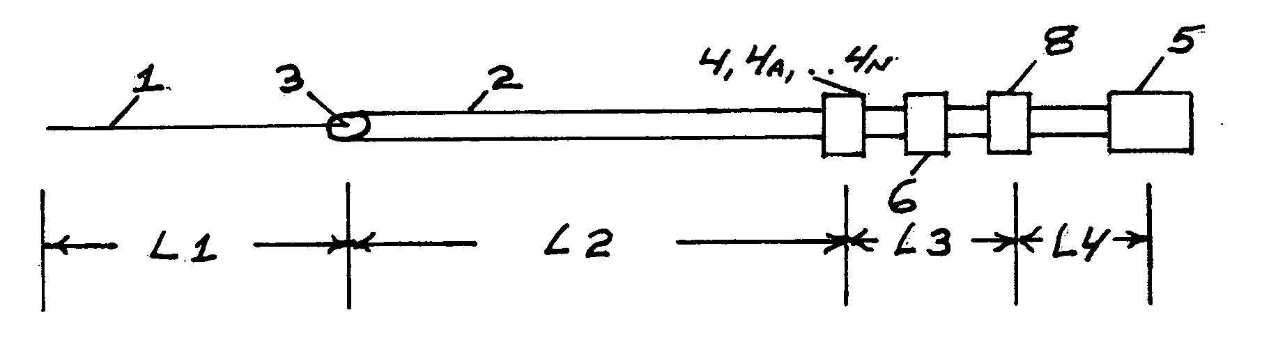
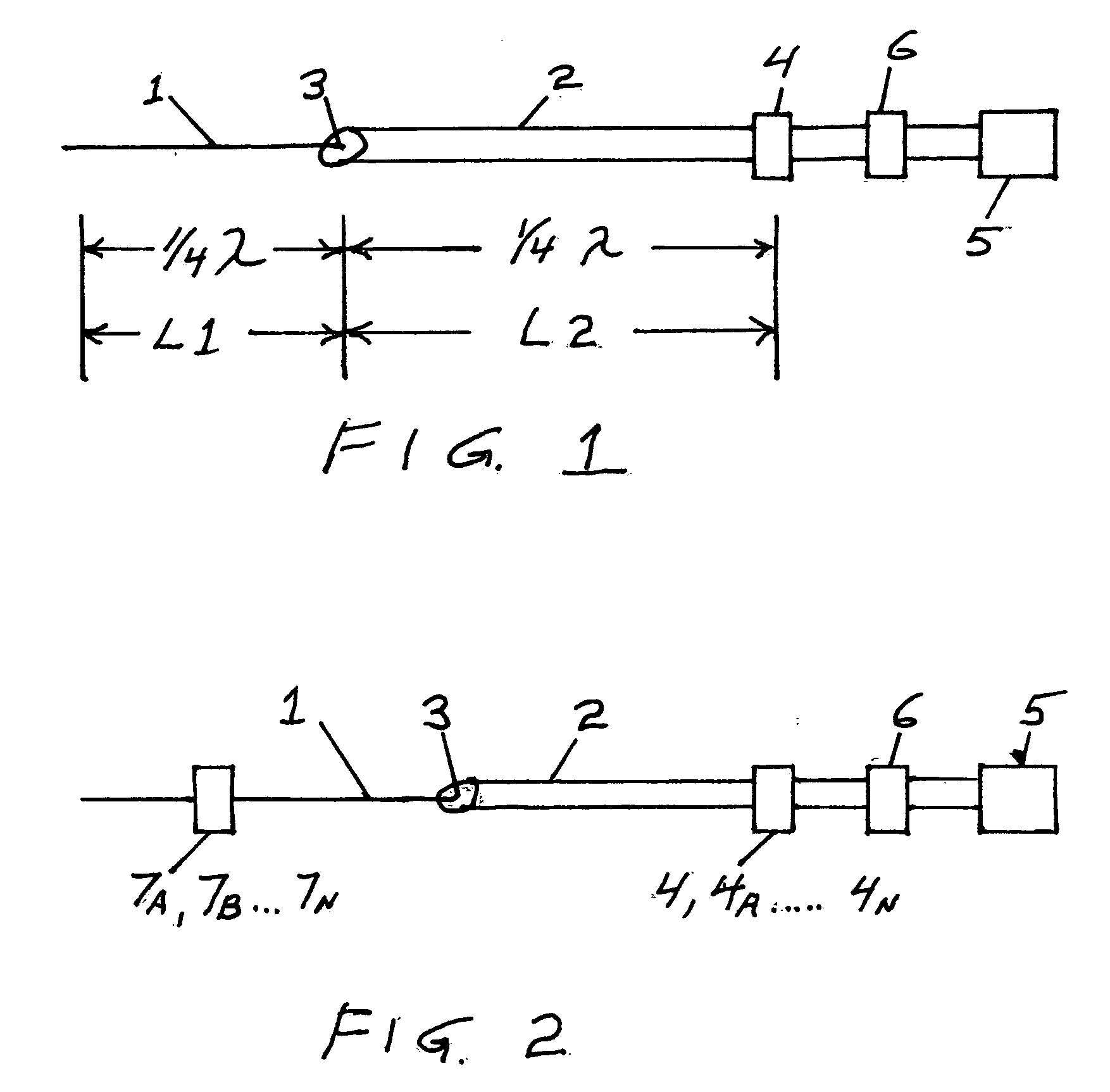
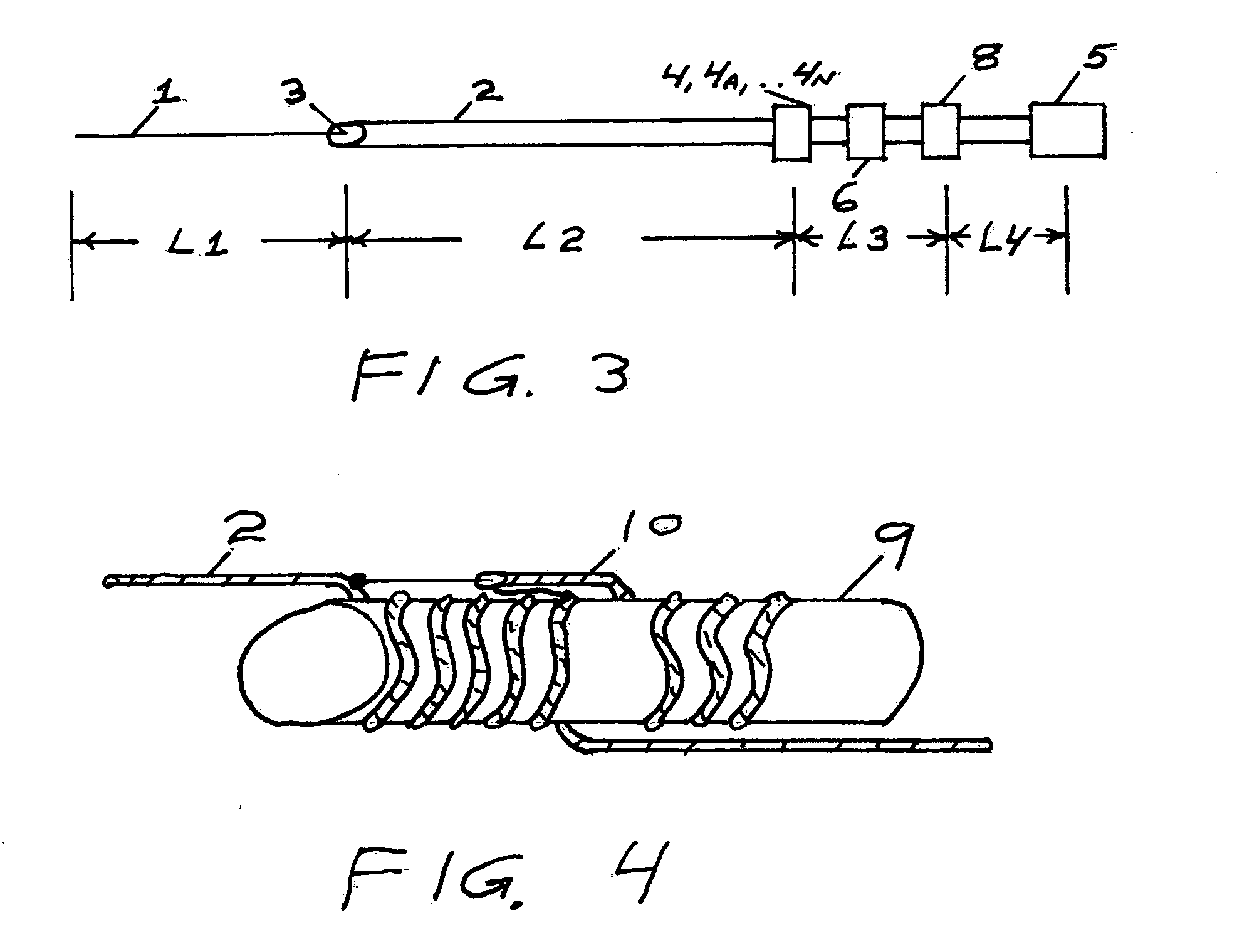
[0017]Referring to FIG. 1, the simplest embodiment of this invention will be used to help explain the invention concept. This embodiment would be a single band coaxial cable dipole antenna for the HF band. It consists of a quarter wavelength wire antenna element 1 connected to the center conductor of the coaxial cable 2. This connection forms the feed point 3 of the dipole antenna. A parallel resonant circuit 4 is placed a quarter wavelength from the feed point 3 along the coaxial cable 2. This parallel resonant circuit defines the electrical length of L2 by presenting high impedance at the resonant frequency and allowing a voltage node to form. An RF choke 6 made of ferrite sleeves is slid over the end of the coaxial cable 2, and the coaxial cable is then connected, to the radio wave circuit 5. The RF choke 6 reduces any chance of stray RF currents from flowing across the coaxial cable.

[0018]Referring to FIG. 1, it should be noted that at radio frequencies the outside surface of th...


PUM


Abstract

An HF dipole antenna apparatus is provided which uses a coaxial cable for both a radiating element and a transmission line. Coiling the coaxial cable and adding a capacitive reactance to form a parallel resonant circuit with the coaxial cable coil achieves the transition between the radiation element and the transmission line. This antenna includes an upper radiating element. The addition of traps and parallel resonant circuits can be made to provide multi-frequency operation. An antenna coupling network can be added that provides appropriate reactance to allow both shortening the length of the dipole and provides a significantly wider range of operating frequencies.

Description

CROSS REFERENCE TO RELATED APPLICATIONS [0001]APPLICATION No. 61 / 135,417 FILED Jul. 21, 2008[0002]INVENTOR: HAROLD JAMES KITTEL[0003]CONTENT RELATIONSHIP: CONVERSION OF PROVISIONAL PATENT TO NONPROVISIONAL PATENTSTATEMENT REGARDING FEDERALLY SPONSORED RESEARCH OR DEVELOPMENT[0004]NOT APPLICABLEREFERENCE TO SEQUENCE LISTING, A TABLE, OR A COMPUTER PROGRAM LISTING COMPACT DISC APPENDIX[0005]NOT APPLICABLEBACKGROUND OF THE INVENTION[0006]High frequency (HF) portable communications systems operating on multiple frequencies through out the 2-30 Mhz frequency range typically use a vertically polarized quarter wave monopole antenna and associated counterpoise or ground plane. The ground plane requires multiple radial wires (as many as 16) or large metal surfaces to be completely effective. Such ground planes are difficult to properly install and difficult to maintain in harsh environments. This is particularly true in maritime applications where salt spray, mechanical stress and vibration ...

Claims


Application Information

Patent Timeline
Patent Type & Authority Applications(United States)
IPC IPC(8): H01Q1/50
CPCH01Q9/16H01Q5/335H01Q5/321
Inventor KITTEL, HAROLD JAMES
Owner KITTEL HAROLD JAMES
Why Eureka
Try Eureka