Electric power unit for induction heating

a technology of induction heating and electric power unit, which is applied in the direction of electric/magnetic/electromagnetic heating, process and machine control, instruments, etc., can solve the problem of inverter possibility, and achieve the effect of simple structure and large current capacity

Inactive Publication Date: 2010-01-21
TOKYO INST OF TECH
View PDF7 Cites 20 Cited by
  • Summary
  • Abstract
  • Description
  • Claims
  • Application Information

AI Technical Summary

Benefits of technology

[0013]The object of the present invention, therefore, is to provide an electric power unit for induction heating which utilizes the merits of MERS, does not need an AC power supply with a large current capacity, and yet has a simple structure comprising a small number of elements and can generate alternate pulse current.

Problems solved by technology

However, it was only possible for the inverter, for the induction heating device, using a fixed resonance capacitor to improve the power factor thereof only at a frequency specified by L and C.

Method used


Image

  • Electric power unit for induction heating
  • Electric power unit for induction heating
  • Electric power unit for induction heating

Examples


embodiment 1

[0033]A simulation circuit is shown in FIG. 5. The circuit constants are as follows:

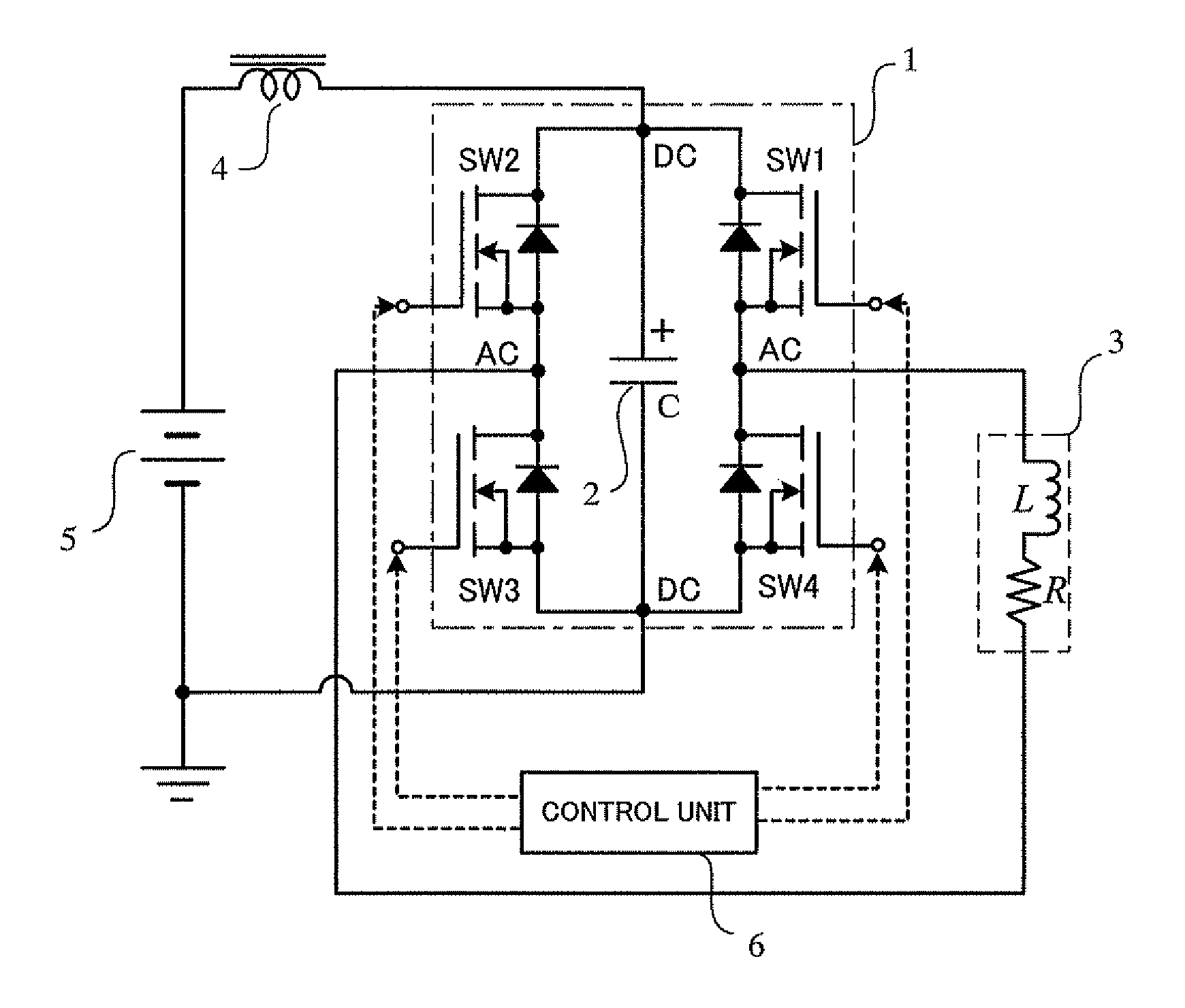
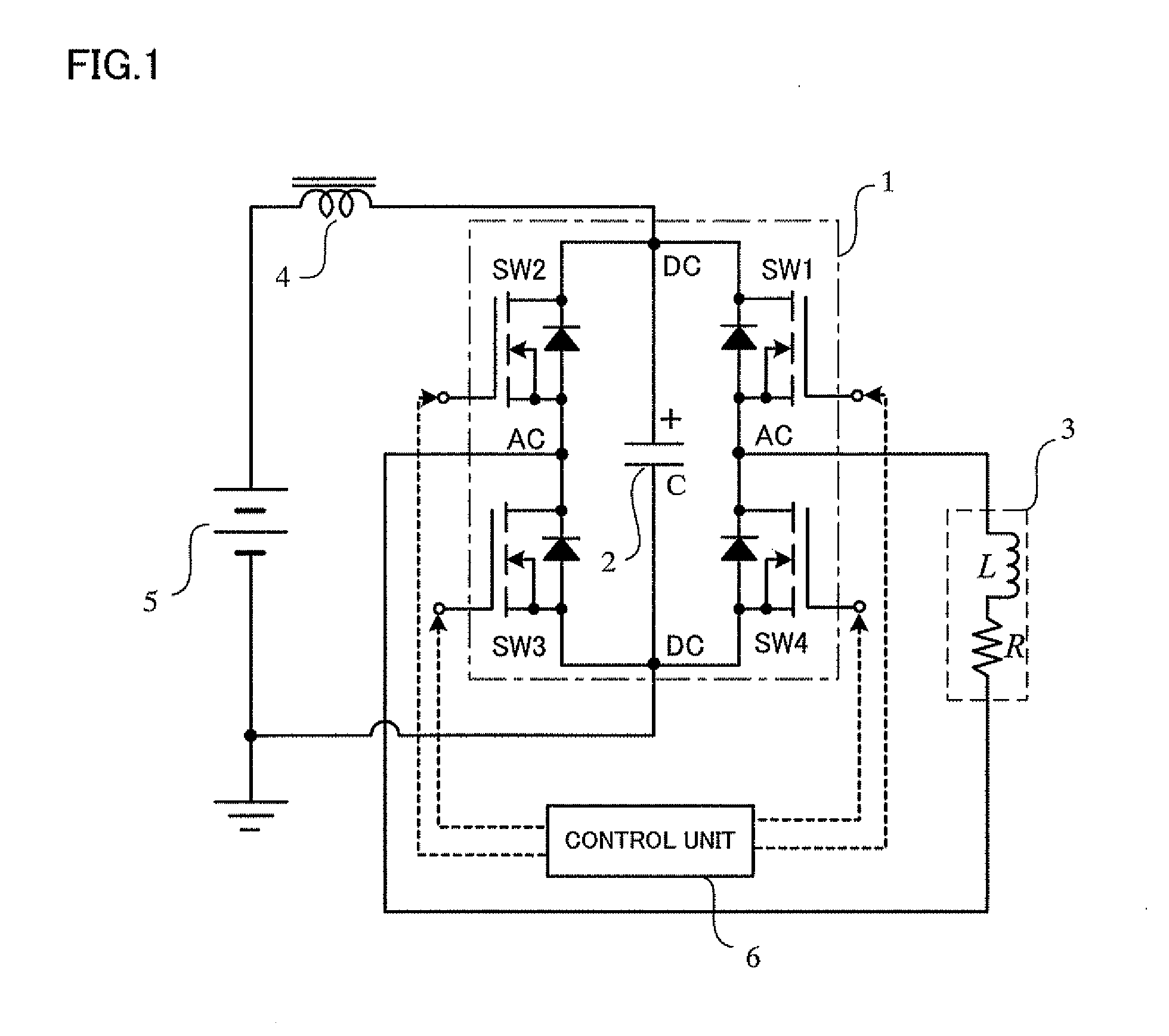
[0034]energy storage capacitor 2: C=0.47 μF

[0035]inductive load coil 3: L=1 mH

[0036]equivalent resistance: R=5Ω

[0037]current source inductance 4 (smoothing coil): L=40 mH

[0038]DC power supply: A voltage obtained by rectifying AC 100V by a bridge diode 7 The explanation of the circuit operation and rough estimates of the input power and output are as follows:[0039](1) As the power supply is connected through a large inductance 4, a current with a few ripples is flown.[0040](2) While the capacitor is charged with voltage, constant current Iin flows in and electric power is provided from the power supply. The period when the voltage is being generated in the capacitor is the period of the half cycle of the LC resonance condition between load L and energy storage capacitor C. In one cycle of the alternate pulse current there are twice of such periods and such time T is:

T=2π√(LC)[0041](3) The average volu...

embodiment 2

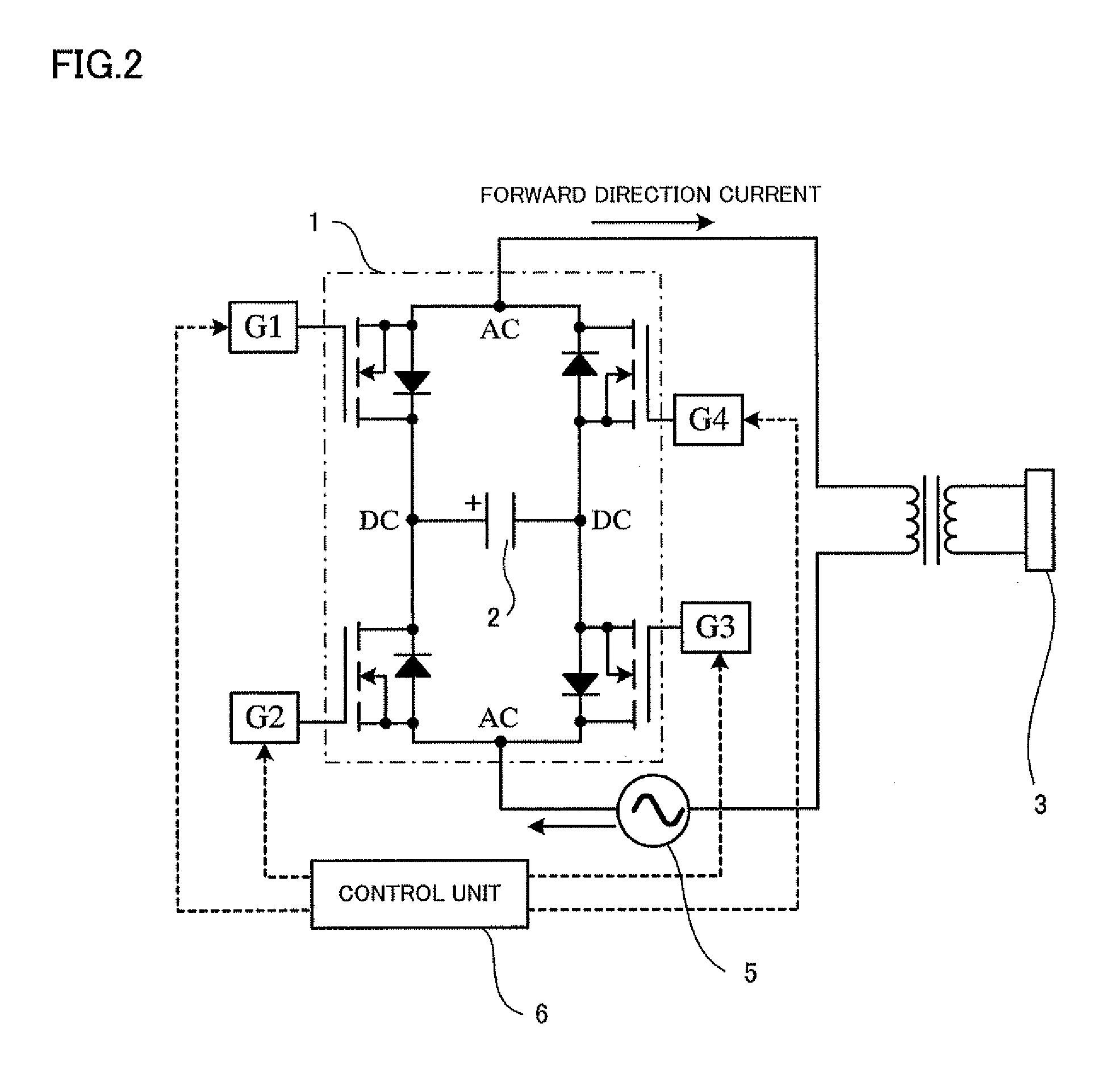
[0051]FIG. 7 shows a circuit diagram of a model experiment and the results thereof. As shown in the figure, when the current is provided from a commercial AC power supply 8 through rectifying bridge diode 7, the AC is in the same phase with the voltage and there is only a little harmonic component from the AC power supply, and yet the AC input power factor is improved.

embodiment 3

[0052]As shown in FIG. 8, the same effect is acquired when magnetic energy recovery switches are constituted by a half bridge circuit structure. That is, the magnetic energy recovery switches comprising a bridge circuit 1 and a capacitor 2 may be replaced by magnetic energy recovery switches in a half bridge structure wherein one arm of the bridge is connected in series with two reverse-conductive type semiconductor switches and the other arm thereof is connected in series with two capacitors, and yet each capacitor is clamped by parallel diodes. While the capacitor will have the capacitance twice larger than the capacitor shown in FIG. 1, there are two switches and the electric current flows through the diodes only for a short time.

[0053]The electric power unit for induction heating according to the present invention has an excellent effect that the alternate pulse current can be generated only by magnetic energy recovery switches (MERS) and yet the frequency of the alternate pulse...


PUM


Abstract

Reverse conducting type semiconductor switches are arranged in a bride from, an energy storage capacitor is connected with its DC terminal to obtain a magnetic energy regeneration switch, and then an induction coil is connected to its AC terminal. An AC pulse current of variable frequency is obtained by applying a gate signal to the semiconductor switch to thereby turn it ON/OFF; since a voltage is generated automatically by regenerating magnetic energy, a DC power supply is connected to the opposite ends of the capacitor through a smoothing coil, thus injecting power.

Description

TECHNICAL FIELD[0001]The present invention relates to an electric power unit for induction heating, more particularly, to an electric power unit for induction heating for supplying a high frequency alternate pulse current to an induction coil (also called a work coil) of an induction heating device.BACKGROUND ART[0002]Conventionally, when flowing an alternate pulse current through an inductance load such as an induction coil for an induction heating device, it is necessary to apply a high voltage from the power supply to change the current, due to the effect of magnetic (snubber) energy stored at the inductance load.[0003]In order to flow the alternate pulse current through the induction coil by a conventional voltage-type inverter comprising semiconductor switches, the inverter must generate voltage corresponding to changes in the electric current. A difference in phase is brought about between the current and the voltage of the inverter, and the power supply becomes a so-called po...

Claims


Application Information

Patent Timeline
Patent Type & Authority Applications(United States)
IPC IPC(8): H02M7/06G05F1/10
CPCH05B6/04
Inventor SHIMADA, RYUICHIKITAHARA, TADAYUKIFUKUTANI, KAZUHIKO
Owner TOKYO INST OF TECH
Why Eureka
Try Eureka