
Device For Longitudinal Pumping Of A Laser Medium

a laser medium and pumping technology, applied in the direction of lasers, laser construction details, semiconductor lasers, etc., can solve the problems of reducing the power of the thermal lens created by the cooling means, the arrangement described in the aforementioned german patent application is inefficient, etc., to achieve uniform pumping of the amplifying laser medium, improve compactness, and operate with high energy levels

Inactive Publication Date: 2010-01-21
CENT NAT DE LA RECHERCHE SCI
View PDF5 Cites 37 Cited by
  • Summary
  • Abstract
  • Description
  • Claims
  • Application Information

AI Technical Summary

Benefits of technology

[0004]A first aim of the present invention is therefore to provide a longitudinal pumping device with improved compactness. Another aim of the present invention is to provide a longitudinal pumping device which can operate with high energy levels. Another aim of the present invention is to provide a longitudinal pumping device which can operate in the presence of a large number of pumping laser diodes. Another aim of the present invention is to provide a longitudinal pumping device for which the pumped zone is separated from the contours of the pumped rod so as to avoid the effects of diffraction. Another aim of the present invention is to allow substantially uniform pumping of the amplifying laser medium.
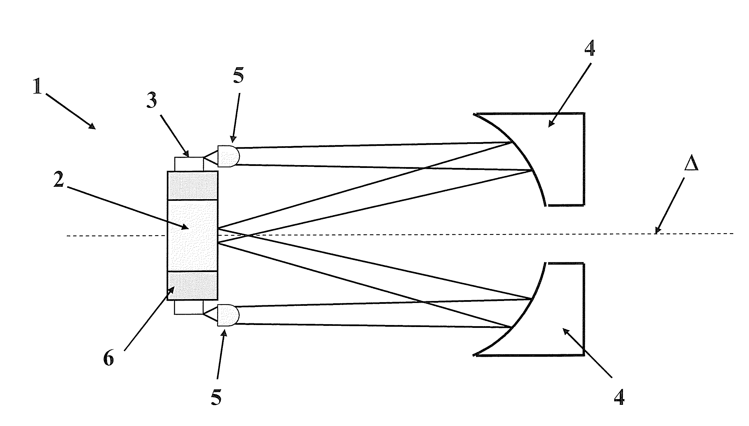
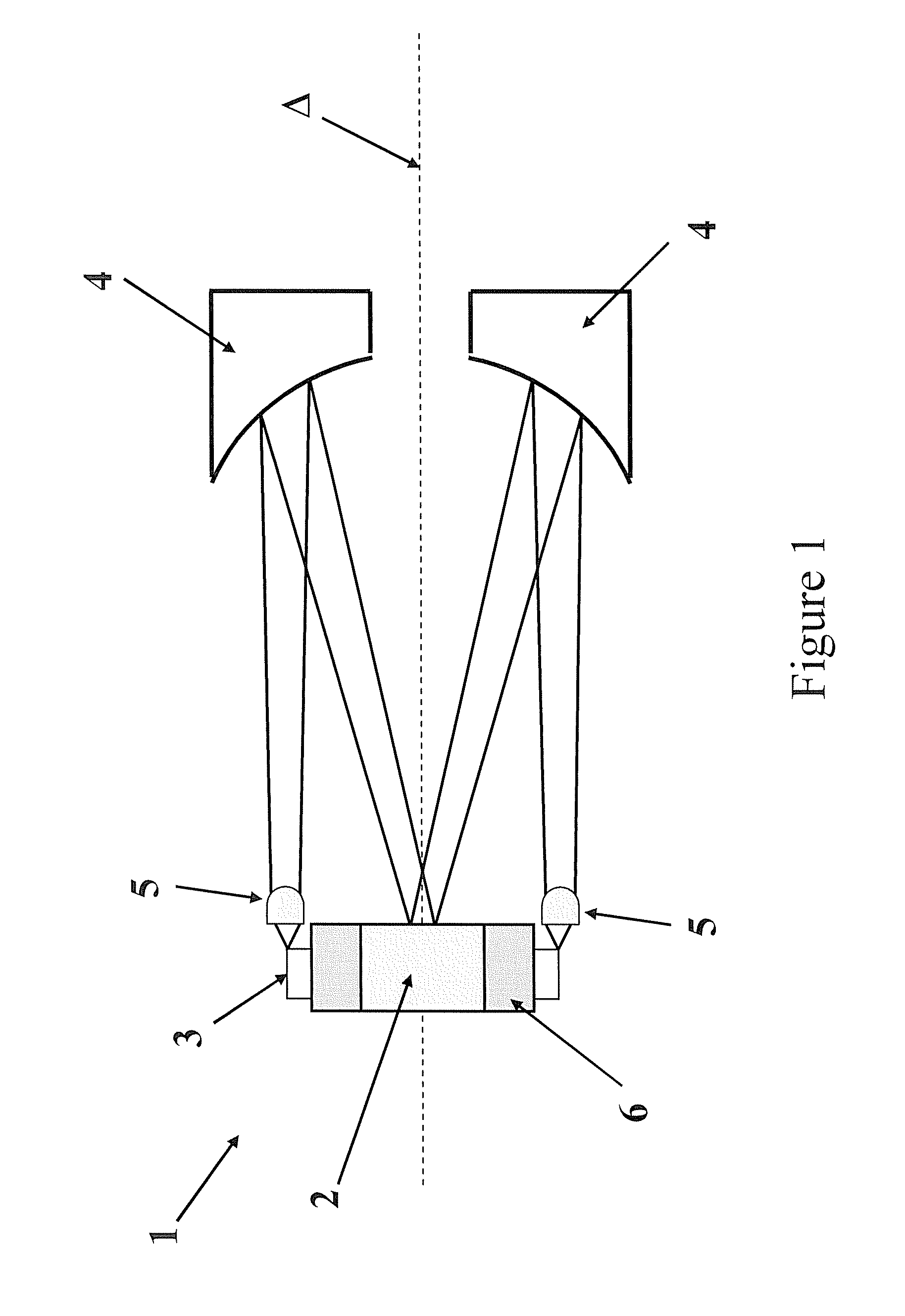
[0005]At least one of the above aims is achieved according to the invention by a device for longitudinal pumping of an amplifying laser medium comprising at least one laser diode capable of emitting at least one laser beam, means for collimating said laser beam capable of generating a collimated laser beam, means for focussing said collimated laser beam onto said amplifying laser medium, characterised in that said focussing means comprise at least one mirror, said mirror being arranged such that said collimated beam is reflected towards said amplifying medium. In order to adapt to the laser rod configurations in which said laser medium is a cylinder, the axis of rotation of said cylinder is positioned according to a longitudinal emission axis of said laser medium and said device comprises a plurality of diodes surrounding said laser medium. Thus, the device according to the invention is compact since the mirrors allow the beams to be reflected towards to the amplifying medium.
[0006]In order to use the standard diode configurations, and thus to reduce the cost of producing the invention, said plurality of diodes is formed by a plurality of diode arrays positioned according to a longitudinal emission axis of said amplifying medium, said device comprising a plurality of mirrors, each one of said mirrors being associated with one of said arrays. The specific association of each mirror with each diode array with which it is associated by the beam makes it possible to adjust the pumped volume. In order to minimise the pumped volume, said arrays are spaced out angularly around said amplifying medium, each one of said arrays defining an angle formed by the axis defined by the straight line between said array and the centre of said mirror associated with said array and the emission axis of said laser medium, said mirror being tilted in relation to the straight line connecting said array and the centre of said mirror associated with said array and the emission axis of said laser medium according to said angle.
[0007]When the device comprises means for cooling said compensating medium, said cooling means being positioned between said at least one diode and said amplifying medium, a non-doped material is preferably positioned between said at least one mirror and said amplifying medium in the trajectory of said reflected beam. This reduces the power of the thermal lens created by said cooling means. For low-energy pumping systems, said device comprises a first laser diode capable of emitting a first laser beam, and a second laser diode capable of emitting a second laser beam, said device comprising a first mirror associated with said first diode and a second mirror associated with said second diode, said amplifying medium comprising a first longitudinal surface and a second longitudinal surface, said first mirror being arranged so as to reflect said first laser beam towards said first surface of said amplifying medium, said second mirror being arranged so as to reflect said second laser beam towards said second surface of said amplifying medium. In order to obtain uniform lighting of said amplifying medium, said at least one mirror is a parabolic mirror.

Problems solved by technology

However, it is understood that in order to perform high-energy longitudinal pumping, and thus to have a large number of laser diodes emitting a large number of laser beams with a low angle of incidence, the arrangement described in the aforementioned German patent application is inefficient due to the plurality of diodes and the need to be focussed by an array of lenses.
This reduces the power of the thermal lens created by said cooling means.

Method used


Image

  • Device For Longitudinal Pumping Of A Laser Medium
  • Device For Longitudinal Pumping Of A Laser Medium
  • Device For Longitudinal Pumping Of A Laser Medium

Examples


first embodiment

[0015]For the purpose of the present application, the term “longitudinal pumping” will be used to refer to a pumping mode in which a pumping beam (or a plurality of beams) is inserted in the amplifying medium by the same optical surfaces as the input or output surfaces of the amplified laser beam. According to the invention shown in FIG. 1, a longitudinal pumping device 1 according to the invention comprises a laser amplifying medium 2 in the form of a laser rod, an array of diodes 3, and one or more folding mirrors 4. It also comprises means for collimating the beam emitted by the diodes, for example in the form of an assembly of lenses 5. It also comprises a device 6 for cooling the diodes 3 and the rod 2, for example positioned between the diodes 3 and the rod 2.

[0016]The arrays of laser diodes 3 form a crown that surrounds the cylindrical solid-state amplifying medium 2, the axis of rotation of the cylinder matching the direction of emission of the laser beam Δ. The beams emitte...

second embodiment

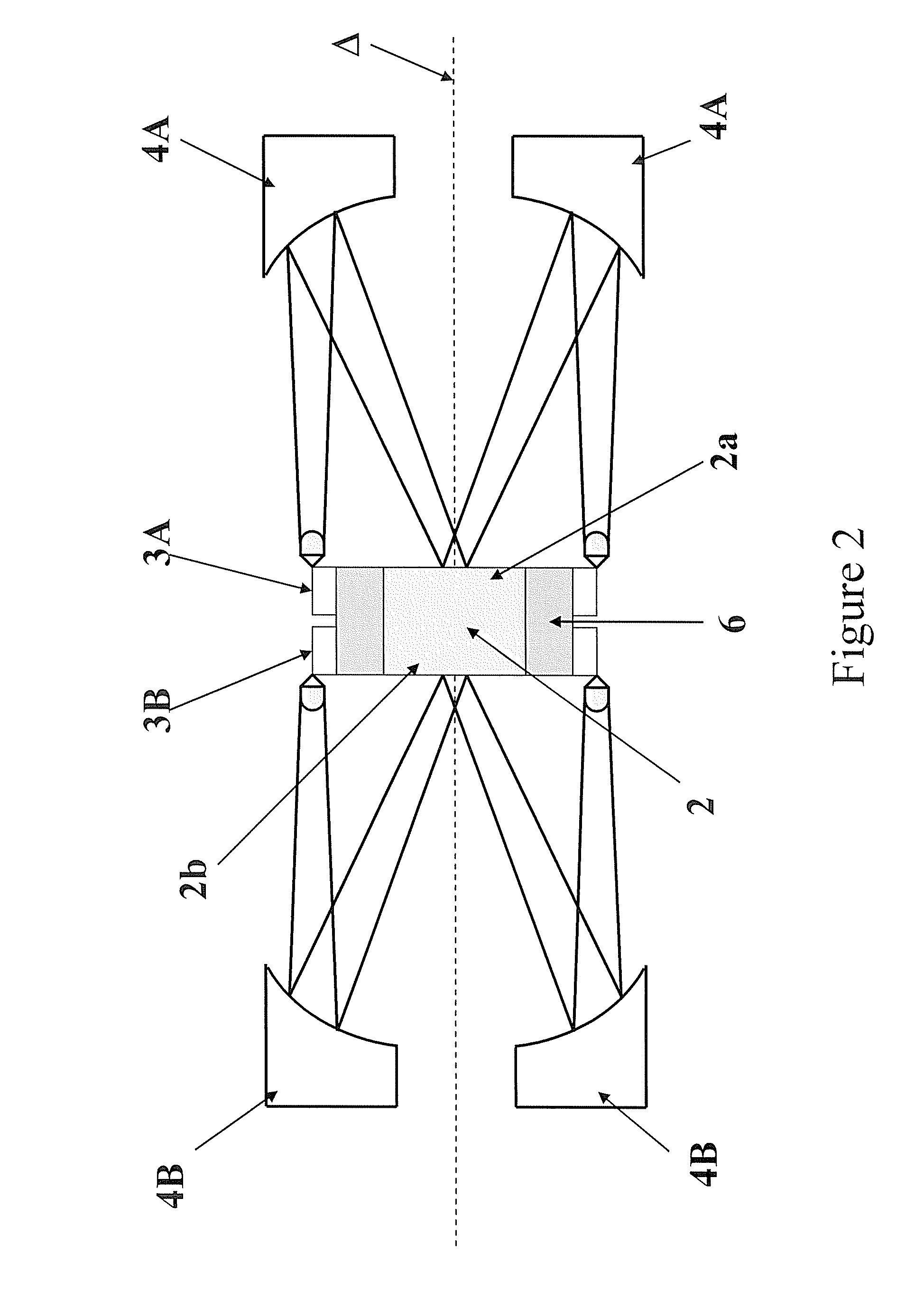
[0017]According to the invention it is also possible to light the laser rod 2 at both its ends. This is shown in FIG. 2 according to the invention in which a laser rod 2 is provided, comprising a first end 2a and a second end 2b, a first crown of diode arrays 3A and a second crown of diode arrays 3B. These two crowns surround the rod 2. The first crown 3A emits a collimated light beam towards a first mirror 4A on the side of the end 2a. This beam is then reflected towards the first end 2a. In the same way, a light beam emitted by the arrays 3B is reflected by a mirror 4B towards the end 2b. In this configuration it is possible, at the same time, to adapt the cross-section of the pumped zone and the diameter of the pump beam to be amplified to optimise the optical output ratio.

[0018]If the cylindrical rod 2 is cooled at its periphery, for example by a cooling device 6, a thermal lens is created rotating around the axis of rotation of the system. One method of reducing the power of th...


PUM


Abstract

The invention concerns a device for longitudinal pumping of an amplifying laser medium comprising at least one laser diode capable of emitting at least one laser beam, means for focusing said laser beam onto said amplifying laser medium and means for collimating said laser beam capable of generating a collimated laser beam. The invention is characterized in that said focusing means comprise at least one mirror, said mirror being arranged such that said collimated beam is reflected towards the amplifying medium.

Description

CROSS-REFERENCE TO RELATED APPLICATIONS[0001]This application is a National Phase Entry of International Application No. PCT / FR2007 / 000143, filed Jan. 25, 2007, claiming priority to French Patent Application No. 06 / 50339, filed Jan. 31, 2006, both of which are incorporated by reference herein.BACKGROUND AND SUMMARY[0002]The present invention relates to the field of devices for longitudinal pumping of an amplifying laser medium. It relates more particularly to a device for longitudinal pumping of an amplifying laser medium comprising at least one laser diode capable of emitting at least one laser beam, means for collimating said laser beam, and means for focussing said collimated laser beam onto said amplifying laser medium.[0003]Such devices are known, for example, from German patent application DE 10235713 relating to a device comprising a plurality of laser diodes each emitting a laser beam. These diodes are axially positioned around the direction of propagation of the laser beam,...

Claims


Application Information

Patent Timeline
Patent Type & Authority Applications(United States)
IPC IPC(8): H01S3/042H01S3/0941H01S3/07
CPCH01S3/042H01S3/0604H01S3/09415H01S3/1618H01S3/2316H01S3/025H01S5/02248H01S5/02438H01S5/4031H01S5/4056H01S5/0071H01S5/02325
Inventor CABARET, LOUIS
Owner CENT NAT DE LA RECHERCHE SCI
Learn More