Assembly for producing a hydrogenous gas

Inactive Publication Date: 2010-01-21
EMCON TECHNOLOGIES GERMANY (AUGSBURG) GMBH
View PDF4 Cites 30 Cited by
  • Summary
  • Abstract
  • Description
  • Claims
  • Application Information

AI Technical Summary

Benefits of technology

[0005]In contrast thereto, the invention provides an assembly for producing a hyd

Problems solved by technology

It became apparent that it is unfavorable to supply the fuel directly in a liquid form to the reformation device because the temperature prevailing in the reformation device greatly decreases, at least in an inlet region of the liquid, owing to the thermal energy needed for vaporizing the fuel.
The amount of energy provided by the reformation device is possibly insufficien

Method used


Image

  • Assembly for producing a hydrogenous gas
  • Assembly for producing a hydrogenous gas
  • Assembly for producing a hydrogenous gas

Examples


Embodiment Construction

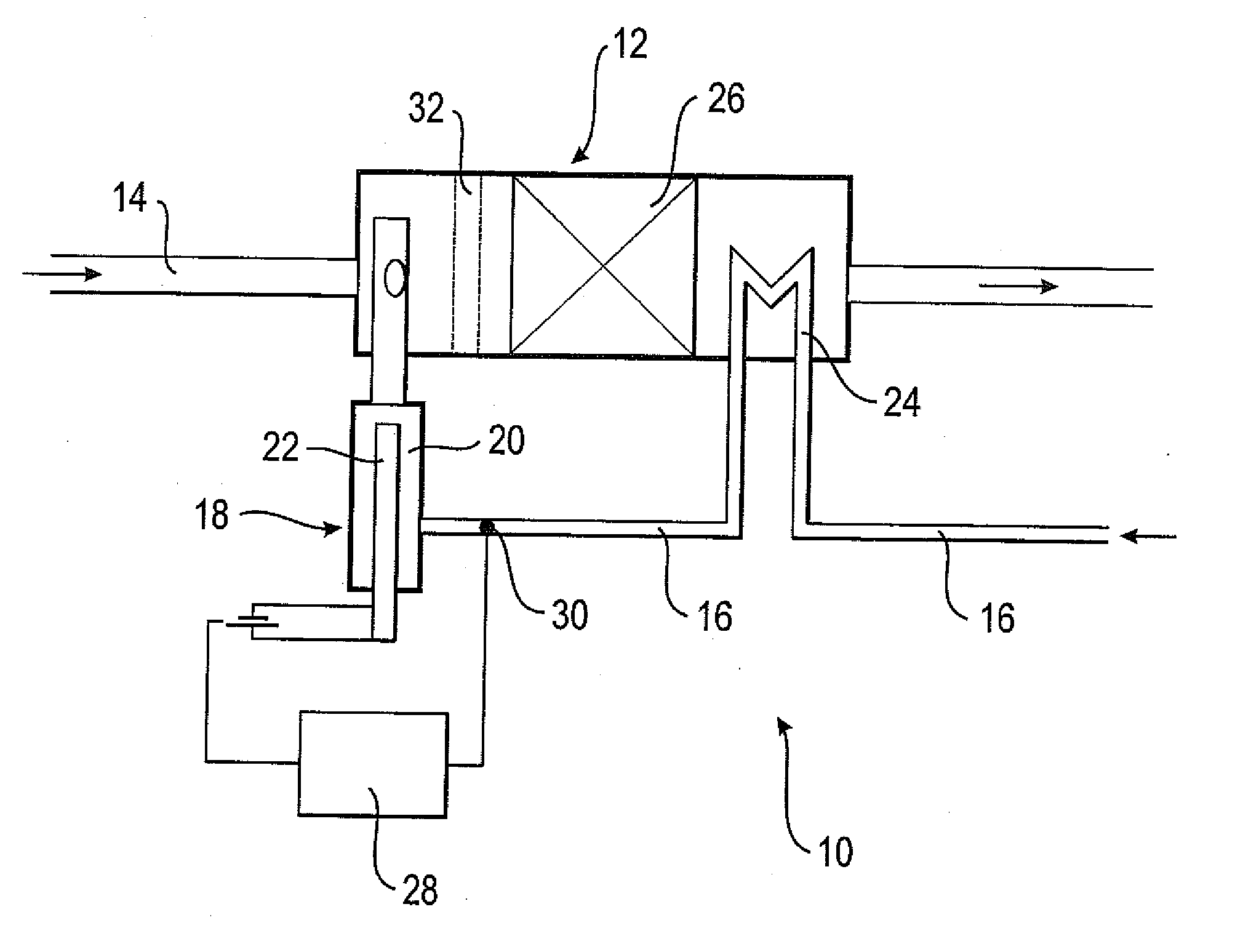
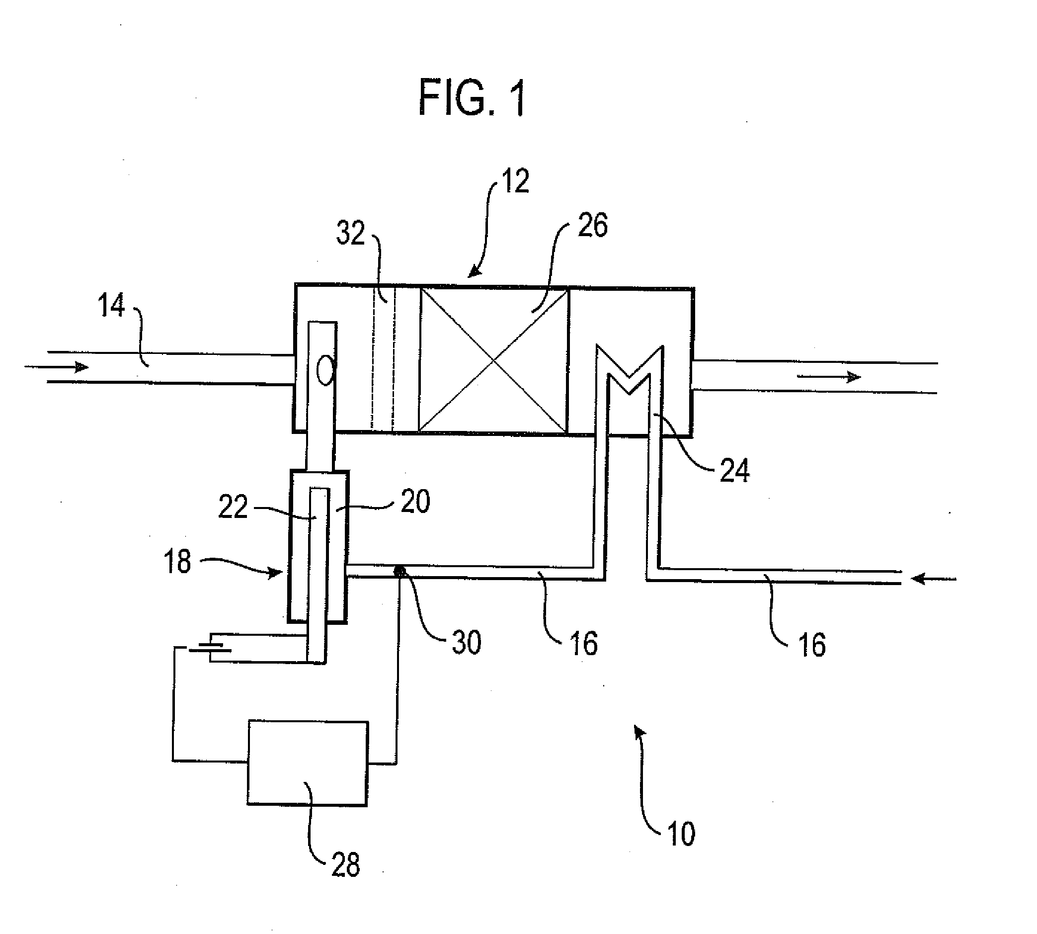
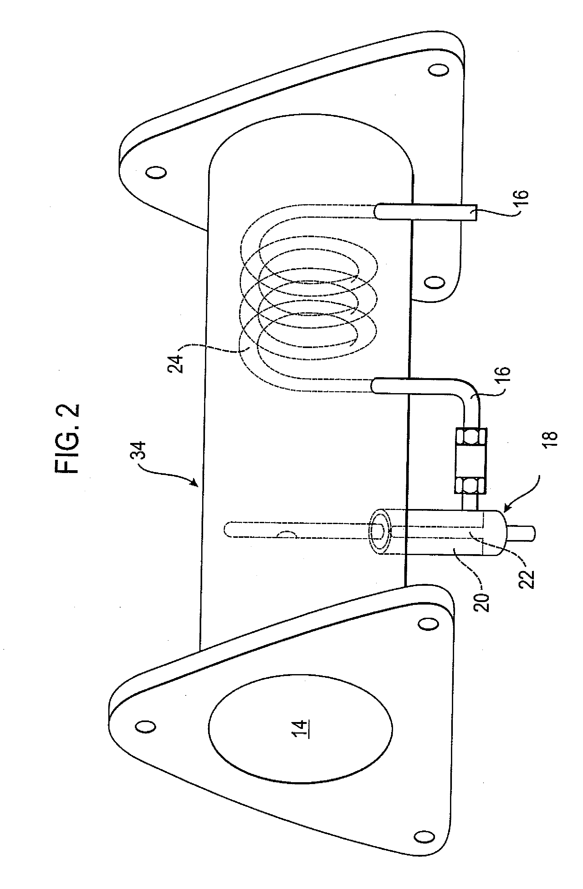
[0020]An assembly 10 for producing a hydrogenous gas comprises a reformation device 12 having a gas supply 14 in the form of an air supply, and a fuel supply 16. A vaporization unit 18 is arranged in the fuel supply 16 and includes an electrical heating element 22, in the present case a glow plug, which is placed in a chamber 20. Alternatively, a ceramic glow pencil (MIMS) can be used as a heating element 22. The vaporization unit 18 is thus located upstream of a catalytic converter 26 of the reformation device 12 with respect to the gas flow passing through the reformation device 12. The catalytic converter is in particular a partial oxidation catalytic converter (POX).

[0021]Arranged upstream of the chamber 20 is a preheating device for the fuel in the form of a heat exchanger 24, which is placed in the reformation device 12 downstream of the catalytic converter 26 in the embodiment shown. The heat exchanger 24 is thus exposed to the gas flow which passes through the reformation de...


PUM


Abstract

An assembly for producing a hydrogenous gas has a reformation device with a fuel supply, a gas supply, and a catalytic converter. A vaporization unit is arranged upstream of the catalytic converter of the reformation device with respect to the gas flow and has a heating element arranged in a chamber for vaporizing a fuel. The vapor is guided into the gas flow and a preheating device for the fuel is arranged upstream of the chamber and configured as a heat exchanger.

Description

RELATED APPLICATIONS[0001]The application is the U.S. National Phase of PCT / EP2007 / 004339 filed 15 May 2007, which claimed priority to German Application 10 2006 025 664.6 filed 1 Jun. 2006.TECHNICAL FIELD[0002]The invention relates to an assembly for producing a hydrogenous gas.BACKGROUND OF THE INVENTION[0003]There exists a wide variety of possible uses for hydrogenous gas, such as in a fuel cell, as a fuel for a combustion engine or for the regeneration of an exhaust gas purification system, for example of a NO,-storage catalytic converter or a particulate filter in the exhaust system of a Diesel or lean mixture engine. Hydrogenous gas can be produced on the basis of a fuel-air-mixture using a reformation device (for example a so-called POX-catalytic converter or an autothermal reformer) by decomposing the mixture into a hydrogen-enriched gas in a catalytic converter of the reformation device.[0004]It became apparent that it is unfavorable to supply the fuel directly in a liquid ...

Claims


Application Information

Patent Timeline
IPC IPC(8): H01M8/18
CPCB01B1/005B01J8/0278B01J8/0285B01J2208/00203B01J2208/00407B01J2208/00716C01B2203/1619C01B2203/0244C01B2203/0261C01B2203/0844C01B2203/085C01B2203/0883C01B2203/1288C01B3/386
Inventor RUSCH, KLAUSRANALLI, MARCO
Owner EMCON TECHNOLOGIES GERMANY (AUGSBURG) GMBH
Why Eureka
Try Eureka