Dynamic desalter simulator

Inactive Publication Date: 2010-01-21
GENERAL ELECTRIC CO
View PDF6 Cites 27 Cited by
  • Summary
  • Abstract
  • Description
  • Claims
  • Application Information

AI Technical Summary

Benefits of technology

[0021]The invention is also directed to a method of testing emulsion breaker chemicals in a dynamic desalter simulator. The method includes the steps of drawing crude oil from a heated and pressurized oil deviblis configured to hold a supply of crude oil and drawing wash water from a water deviblis configured to hold a supply of wash water. At least one emulsion breaker chemical is added to the desalter simulator. The crude oil and wash water are pumped through the desalter simulator with a low shear metering pump and crude oil-wash water emulsion is formed with an emulsion forming device. The method also includes resolving the crude oil-wash water emulsion in a desalter vessel so the wash water and crude oil form distinct phases, with substantially desalted crude oil removed from an upper portion of the desalter

Problems solved by technology

Liquid hydrocarbon phase, such as crude oil, naturally contains a variety of contaminants that have detrimental effects on process equipment and in the operation of a refinery.
The presence of salts, especially chlorides of Group I and Group II elements of The Periodic Table of Elements, causes corrosion of oil processing equipment.
One problem encountered with dewatering and desalting is that some crude oils form an undesirable “rag” layer comprising a stable oil-water emulsion and solids at the water-oil phase boundary in the desalter vessel.
Rag layers at the water-oil phase boundary result in oil loss and reduced processing capacity.
The additives reduce the effective time required for good separation of oil, solids, and water.
These methods have proven to be useful but they often fail to adequately simulate many critical parameters of a desalter and have been of limited use particularly in heavy oils or systems that have a propensity to develop rag layers.
In particular, bottle testing fails to simulate the development of a rag layers since these develop over time in dynam

Method used


Image

  • Dynamic desalter simulator
  • Dynamic desalter simulator
  • Dynamic desalter simulator

Examples


Embodiment Construction

[0026]The invention will now be described in the following detailed description with reference to the drawings, wherein preferred embodiments are described in detail to enable practice of the invention. Although the invention is described with reference to these specific preferred embodiments, it will be understood that the invention is not limited to these preferred embodiments. But to the contrary, the invention includes numerous alternatives, modifications, and equivalents as will become apparent from consideration of the following detailed description.

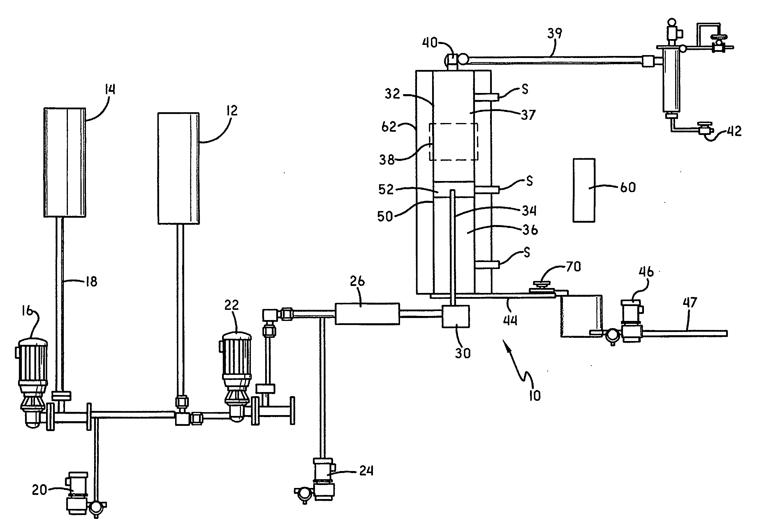
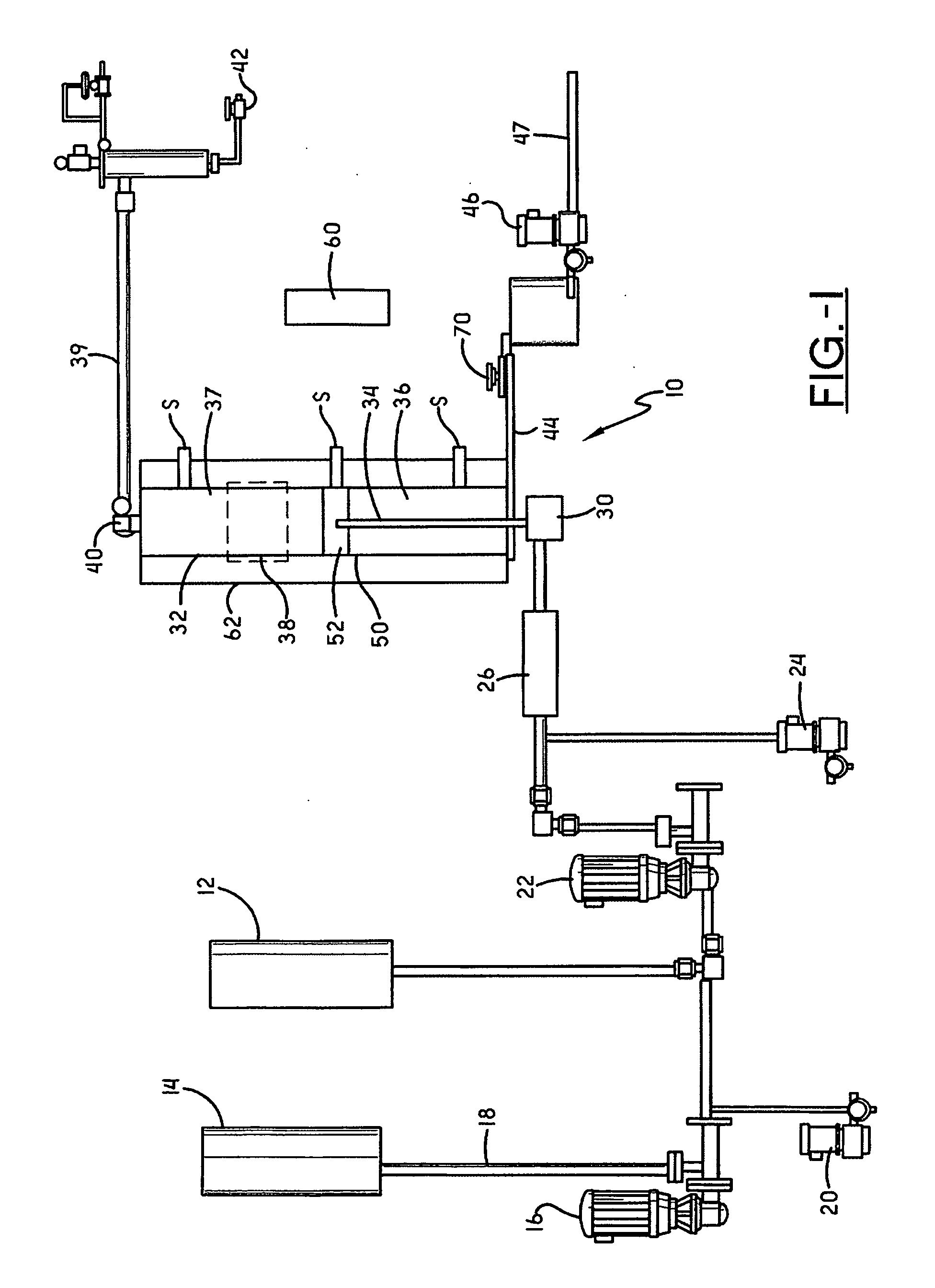
[0027]Referring now to FIG. 1, a desalter simulator 10 is shown that provides the ability to produce operating conditions of a desalter and directly observe the rag layer formed at the oil-water interface as it develops. Additionally, the desalter simulator 10 permits one to observe the development of a rag layer that increases with time and resolves upon the addition of chemical treatment. Testing for the most efficacious chemistr...


PUM

PropertyMeasurementUnit
Temperatureaaaaaaaaaa
Timeaaaaaaaaaa
Volumeaaaaaaaaaa

Abstract

A small-scale dynamic simulator for crude oil refinery desalters has a pressurized oil deviblis configured to hold a supply of crude oil and a water deviblis configured to hold a supply of wash water. At least one chemical feed pump selectively adds emulsion breaker chemicals to the desalter simulator and a low shear metering pump is configured to pump crude oil and wash water through the desalter simulator. An emulsion forming device forms a crude oil-wash water emulsion that is then received in a desalter vessel. The desalting vessel is fitted with electric grids which simulate those found in electric desalters. The emulsion is resolved within the desalter vessel with the assistance of the emulsion breaker chemicals so the wash water and crude oil form distinct phases, with substantially desalted crude oil removed from an upper portion of the desalter vessel and substantially oil-free wash water removed from a bottom portion of the desalter vessel. A portion of the desalter vessel is substantially transparent to allow visualization of the demulsification process and at least one light source is positioned adjacent to the desalter vessel to aid in visualization of a rag layer formed in the desalter vessel. A heated jacket surrounds the desalter vessel to maintain the desalter vessel at the desired temperature.

Description

BACKGROUND OF THE INVENTION[0001]1. Field of the Invention[0002]The present invention relates generally to the small-scale simulation of crude oil refinery desalters, free water knockouts and heater treaters, and more particularly, to a dynamic desalter simulator that enables the direct observation of the rag layer at the crude oil and water interface and the ability to remove samples of the fluids or emulsions during the simulation and monitor parameters such as temperature, pressure, conductivity, chloride, and pH.[0003]2. Description of Related Art[0004]Liquid hydrocarbon phase, such as crude oil, naturally contains a variety of contaminants that have detrimental effects on process equipment and in the operation of a refinery. These contaminants are broadly classified as salts, bottom sediment, water, solids, and metals. The types and amounts of these contaminants vary depending on the particular hydrocarbon phase. Additionally, native water present in the liquid hydrocarbon phas...

Claims


Application Information

Patent Timeline
IPC IPC(8): G01N21/00G01N21/01B01F23/00C09K23/00
CPCC10G31/08G01N21/01G01N21/5907Y10T436/25C10G2300/805Y10T436/25375Y10T436/25125C10G2300/1033C10G33/04B01F23/00C09K23/00
Inventor MCDANIEL, CATO R.EGGERT, HAROLD J.SOLOMON, KEVIN S.SIDERS, EARL E.DENNISON, FRANKGOLIASZEWSKI, ALAN E.ENGEL, DAVID B.ELDIN, SHERIFBROW, THOMAS K.
Owner GENERAL ELECTRIC CO
Why Eureka
Try Eureka