Equalizer system for emitting a quas i-constant power output RF signal in a frequency band

Inactive Publication Date: 2010-01-21
ST ERICSSON SA
View PDF8 Cites 34 Cited by
  • Summary
  • Abstract
  • Description
  • Claims
  • Application Information

AI Technical Summary

Benefits of technology

[0015]The first resonant circuit improves the transmission properties of the system inside the frequency band. The second resonant circuit improves the current through the antenna for the lower frequencies inside the first frequency band where there is a degradation of the power of the RF signal. The resonant circuits may share some of their components and may provide different types of resonance e.g. series or parallel.
[0018]In order to avoid interferences with other transmitters, which may be in the same device comprising the antenna system as e.g. a portable phone, the wherein the feeding circuit comprises band—reject filters having their resonant frequencies in the frequency bands allocated to higher wireless frequency standards.

Problems solved by technology

The problem with small antennas is that they have a very low radiation resistance, which determines in practice a very low efficiency.
If this problem is not solved the received signal strength by a FM radio for frequencies besides the resonance frequency is too low for good quality reception and noise will be introduced in the audio signal or it can happen that the received signal will not be detected by the FM radio.

Method used


Image

  • Equalizer system for emitting a quas i-constant power output RF signal in a frequency band
  • Equalizer system for emitting a quas i-constant power output RF signal in a frequency band
  • Equalizer system for emitting a quas i-constant power output RF signal in a frequency band

Examples


Embodiment Construction

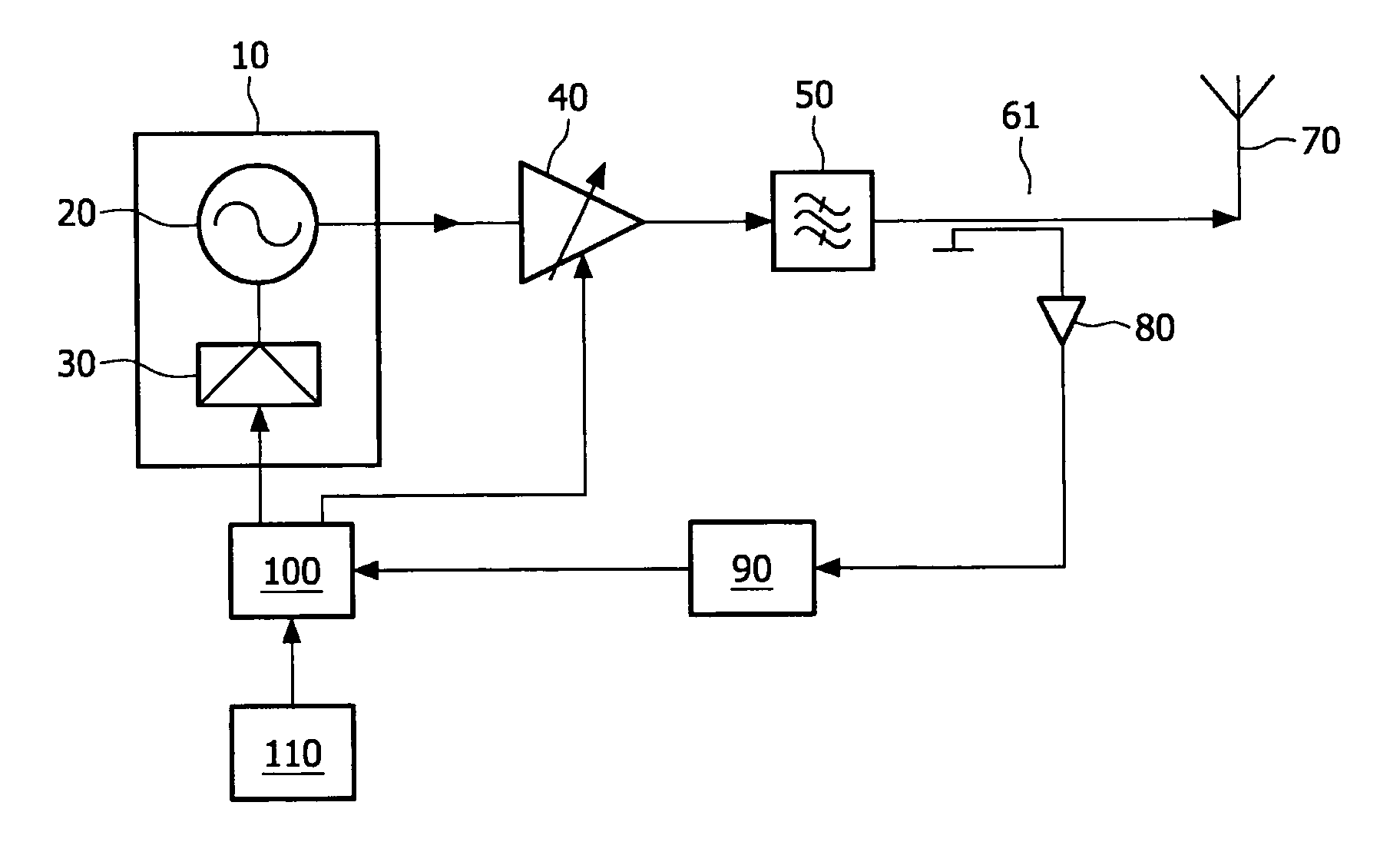
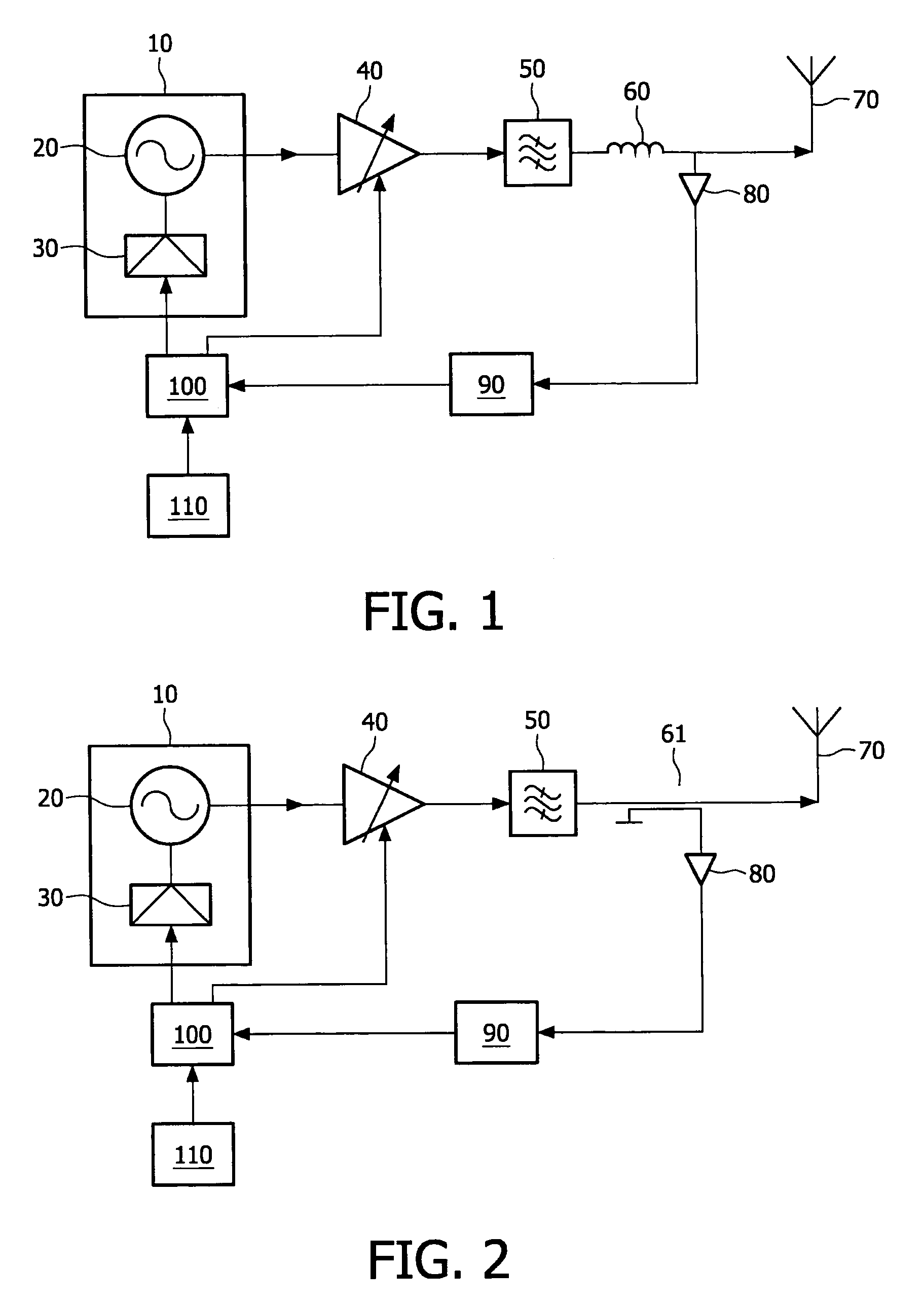
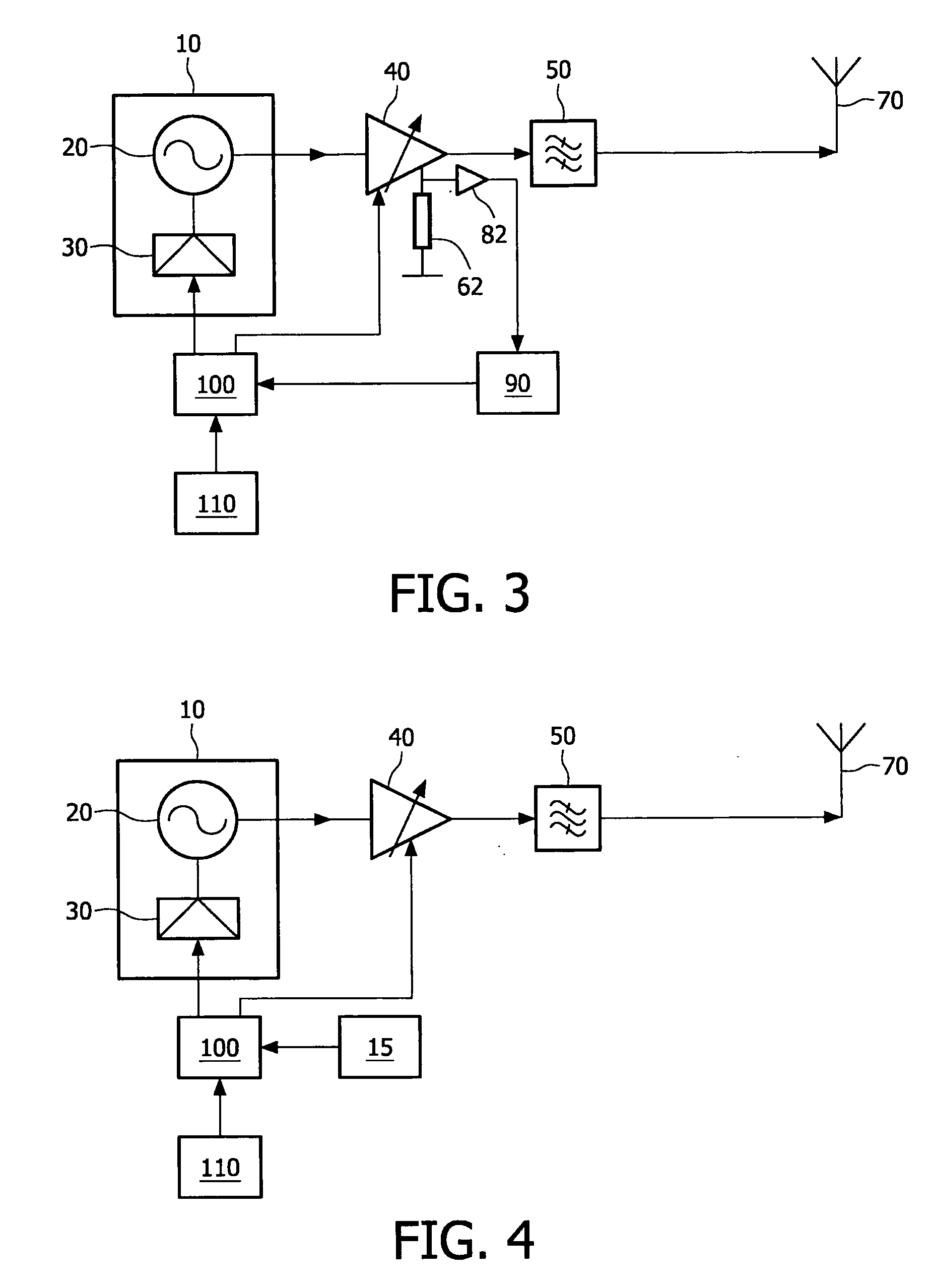
[0027]FIG. 1 and FIG. 2 are embodiments of an equalizer. An audio signal that should to be transmitted is modulated in RF signal generator 10, which may comprise a stereo multiplex mixer-FM modulator 30 and a programmable RF signal oscillator 20. The RF signal oscillator 20 determines the transmit frequency, which is for example in the FM broadcast band. The stereo mixer-FM modulator 30 processes the left and right audio source to a compatible audio signal for a normal broadcast receiver. The FM modulated radio signal from unit 10 is amplified by a variable gain amplifier 40. The amplified radio signal is passed through a filter 50 for removing all unwanted signals, like for example harmonic signals of the transmit frequency. The filtered radio signal is passed trough a current transformator 60 and further to the short antenna 70. The antenna 70 is radiating the radio signal to the broadcast FM receiver. In FIG. 1, the antenna current is for example measured with a current transform...


PUM


Abstract

The invention refers to an equalizer system for emitting a quasi-constant power output RF signal in a first frequency band, the system comprising a programmable RF signal generator (10) for providing a modulated signal; a variable gain amplifier (40) for receiving the modulated signal and generating a RF signal to an antenna (70). The system further comprises a sensing devices (60, 61, 62) for providing a sensing signal which is either a signal proportional with the RF signal or a signal proportional with a supply current of the variable gain amplifier and a user interface (110) for determining an initial RF frequency signal and adjusting circuit (100) for providing a control signal to the variable gain amplifier (40) based on the initial RF frequency signal and the sensing signal, the adjusting circuit (100) comprising an arithmetic unit for calculating a value of the control signal.

Description

FIELD OF THE INVENTION[0001]The invention relates to an equalizer and to a transmitter adapted to use such an equalizer.BACKGROUND OF THE INVENTION[0002]Equalizers are known devices used to correct typically the non-linearity of devices such that a transfer function becomes almost linear in a certain range of interest. Such an application is a transmitting device for transmitting audio content to a FM receiver within a short range e.g. several meters in a standard broadcasting range as 88-108 MHz. In such an application it is important that the transmission power is very low as e.g. 11 nW in US.[0003]Throughout the present application we consider that the term “small antenna” refers to an antenna having its physical dimensions much smaller that the wavelength of the signal transmitted via said antenna i.e. the carrier. Let us observe that in known broadcasting systems the antenna dimensions is a fraction of the wavelength of the carrier e.g. ¼, and that in this application we refer ...

Claims


Application Information

Patent Timeline
IPC IPC(8): H04B1/04
CPCH03G3/3042H04W52/52H04B2001/0416
Inventor KERSELAERS, ANTHONY
Owner ST ERICSSON SA
Why Eureka
Try Eureka