Solar Energy Harvesting Apparatus

Inactive Publication Date: 2010-01-28
B PODS HLDG PTY LTD
View PDF15 Cites 36 Cited by
  • Summary
  • Abstract
  • Description
  • Claims
  • Application Information

AI Technical Summary

Benefits of technology

[0049]The elements may be fully integrated with coolant fluid and electrical connections all fully sealed to ensure maximum life and reliability, with the outer casing/PV cell/substrate/cooling jacket designed and manufactured as a complete single unit. The inner workings (PV cell and coolant jacket) may be fully enclosed by

Problems solved by technology

The modules tend to be smaller because of the higher cost of the mould and the limited strength of the resulting polymeric frame with its integral mounting holes.
For crystalline silicon modules, the backskin material is generally quite costly.
There are two widely used backskin materials, both of which tend to be expensive.
Two additional layers of material are often deployed between the solar cells in the module and the backskin, further adding to the manufacturing costs.
The labour intensive process of mounting the module can add significantly to the overall cost of solar electricity.
However, solar cell modules are often located in remote areas which have no other source of electricity.
As such, the mounting process often involves attaching the hardware in difficult, awkward and not readily accessible locations such as on rugged terrain, or roof tops.
The aforesaid discussion demonstrates that the manufacture of solar cell modules tends to be too costly and involves too much labour to allow for the realization of the goal of cost-competitive solar power.
The problem with that method is that the adhesive or caulking material readily degrades especially in, e.g., a rooftop environment where it is exposed to sun and increases its temperature, or open to wind and rain.
If the adhesiv

Method used


Image

  • Solar Energy Harvesting Apparatus
  • Solar Energy Harvesting Apparatus
  • Solar Energy Harvesting Apparatus

Examples


Embodiment Construction

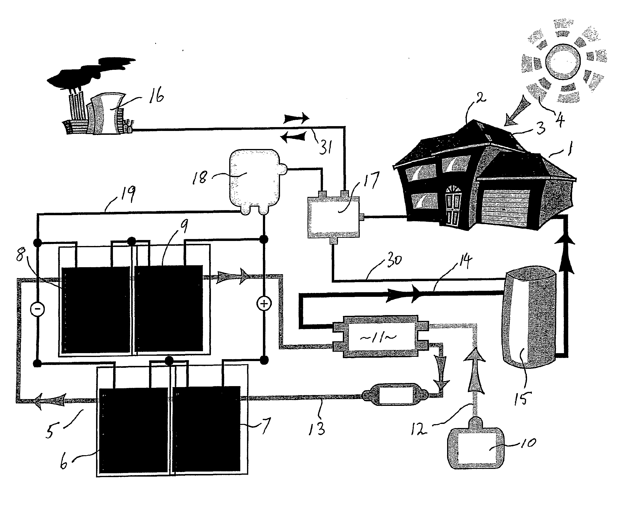
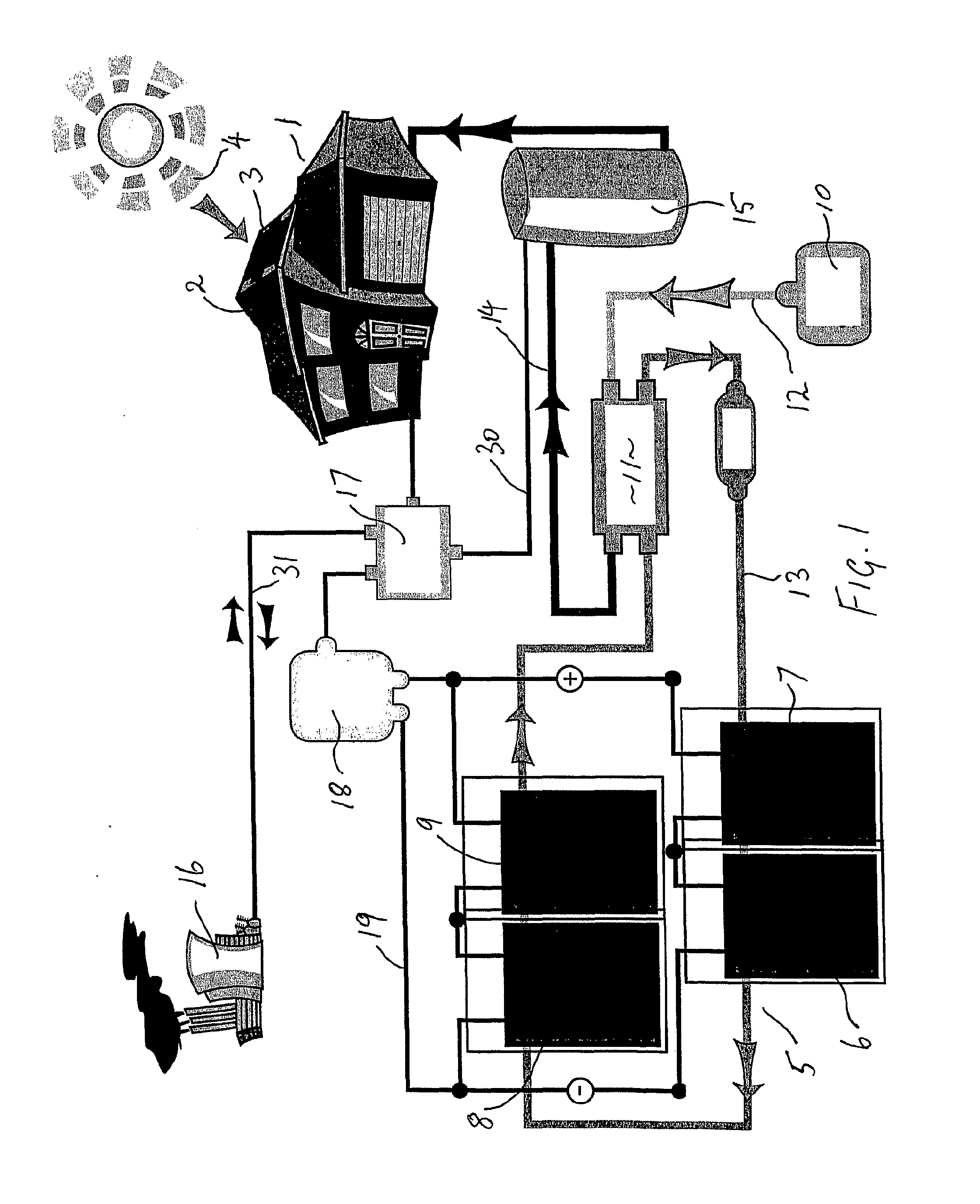
[0063]The arrangement shown in FIG. 1 comprises a dwelling 1 having a roof 2, which has located thereon an array 3 of PV / thermal solar cell elements, which receive solar rays 4. Array 3 is shown in an enlarged configuration 5, which comprises sets of elements 6, 7, 8 and 9. Water supply 10 provides a source of cold water to heat exchanger 11 via inlet pipe 12. Exchanger 11 delivers a coolant to elements 6, 7, 8, and 9 via coolant line 13. Elements 6 and 7 are in parallel with elements 8 and 9. Coolant line 13 takes supercharged coolant back to the heat exchanger, which heats water and delivers hot water via line 14 to hot water tank 15 for consumption in house 1. The system described thus far is similar to known solar systems for creating hot water except that in the embodiment shown the elements 6, 7, 8 and 9 are adapted to an existing tile roof.

[0064]On the power side, the house 1 is conventionally served by a mains AC grid, symbolically represented by the power station 16, by a s...


PUM

PropertyMeasurementUnit
Temperatureaaaaaaaaaa
Transparencyaaaaaaaaaa
Reflectionaaaaaaaaaa

Abstract

There is provided solar energy harvesting apparatus (20) including a clear polycarbonate body (21) including a transparent front face (23) and supporting a thermal absorber (27) adapted to absorb incident solar radiation. The thermal absorber (27) transfers heat via a fluid connector (28) to a circulated-fluid system and in addition controls the temperature of a photovoltaic element (24) mounted on the absorber (27) and connected to an electrical harness by electrical connectors (25, 26). The polycarbonate body (21) has complementary edge mating profiles (32, 33) engaging with a standard-tiled roof structure to replace some of the standard tiles thereof, and is secured conventionally to roof battens by a batten screw (29).

Description

BACKGROUND[0001]The present invention relates to a solar energy harvesting apparatus, energy systems including the apparatus and methods of harvesting solar energy utilizing the apparatus. This invention has particular application (but is not limited to) roof mounted solar energy harvesting systems for domestic and industrial use, and for illustrative purposes the invention will be further described with reference to this application. The invention may find application in other methods and systems for harvesting solar energy including wall mounted and ground-based “broad acre” systems.PRIOR ART[0002]The following examples of prior art apparatus are mere public knowledge are not to be construed as forming part of the common general knowledge in the art.[0003]There are in existence a wide variety of solar energy systems including those which are installed on a roof of a structure such as a dwelling and which capture, via solar cells, solar energy which may be converted into an alterna...

Claims


Application Information

Patent Timeline
IPC IPC(8): H01L31/052H01L31/00F24J2/34F24S23/30F24S90/00
CPCE04D1/20E04D1/24F24J2/0455F24J2/08F24J2/506Y02B10/12H01L31/0547Y02B10/70Y02E10/44Y02E10/52Y02E10/60H02S40/44H01L31/0543Y02B10/20F24S20/69F24S23/30F24S80/525Y02B10/10Y02E10/40
Inventor MITCHELL, KEITHBRAAT, SEBASTIAN
Owner B PODS HLDG PTY LTD
Why Eureka
Try Eureka