
Sparkplug, in Particular for High Combustion Chamber Pressures

Inactive Publication Date: 2010-01-28
ROBERT BOSCH GMBH
View PDF10 Cites 6 Cited by
  • Summary
  • Abstract
  • Description
  • Claims
  • Application Information

AI Technical Summary

Benefits of technology

[0006]The spark plug according to the present invention has the advantage that it prevents the occurrence of creepage sparks. As a result, the spark plug according to the present invention can be used especially in internal combustion engines with high pressures, such as turbocharged and / or high-compression engines. The spark plug according to the present invention exhibits a long service life and can be manufactured simply and economically. This is achieved, according to the present invention, by the fact that a conductive planar element that is electrically in contact with the housing is disposed on the insulator of the spark plug. What is achieved as a result, according to the present invention, is that the insulator surface is brought to the electrical potential of the housing. The housing is usually grounded. By way of this relatively simple action according to the present invention, electric fields that are present in conventional spark plugs, in the breathing space between the tapering insulation and the housing, are eliminated. The generation of creepage sparks can thereby be prevented even at high pressures. In addition, partial discharges in the housing land region can be avoided, and electromagnetic interference pulses can thus also be suppressed.
[0008]The conductive planar element may be disposed in the region of a sealing seat between the housing and the insulator. Secure contacting can be achieved thereby.
[0011]As an example embodiment, the conductive planar element is disposed on the insulator on a region of the insulator that, in the installed state, is located at the height of an internal circumferential land of the housing. The conductive planar element preferably covers, on the insulator, at least 70% of the surface of the insulator that is directed toward the inner land of the housing in the radial direction of the spark plug. This feature ensures that the space between the inner land of the housing and the insulator, which space is susceptible to the formation of electric fields, is at least 70% covered by the electrically conducting element. As a result, this region susceptible to predischarges can be made field-free, so that the tendency for creepage sparks to occur is reduced. Be it noted further that the conductive planar element on the insulator must not extend too far in the direction of the electrodes, since otherwise a shunt susceptibility of the spark plug is substantially increased.
[0014]The conductive planar element is a conductive coating, for example. This can be applied easily and economically, and has only a low density.
[0015]The coating may be a conductive paint that has an electrical conductivity. This has the advantage, in particular, that the coating can be applied particularly easily and economically. It is also not necessary in this context to modify existing installation procedures for spark plugs. The conductive paint preferably encompasses a noble metal, in particular silver and / or platinum and / or gold and / or iridium and / or rhodium, and / or tantalum and / or nickel and / or carbon, or any oxidation-resistant alloy thereof. Oxidation resistance is important because high temperatures and atmospheric oxygen are present in the combustion chamber.

Problems solved by technology

In the homogeneous mode of the internal combustion engine, such creepage sparks can cause the engine to run unevenly.
In the stratified mode of the internal combustion engine and in operating states with an inhomogeneous mixture distribution, for example with low-temperature starts, creepage sparks result in the frequent occurrence of combustion misfires.
The geometrical dispositions proposed in this context for the electrodes often cannot be maintained, however, as a result of parameters related to installation space.

Method used


Image

  • Sparkplug, in Particular for High Combustion Chamber Pressures
  • Sparkplug, in Particular for High Combustion Chamber Pressures
  • Sparkplug, in Particular for High Combustion Chamber Pressures

Examples


Embodiment Construction

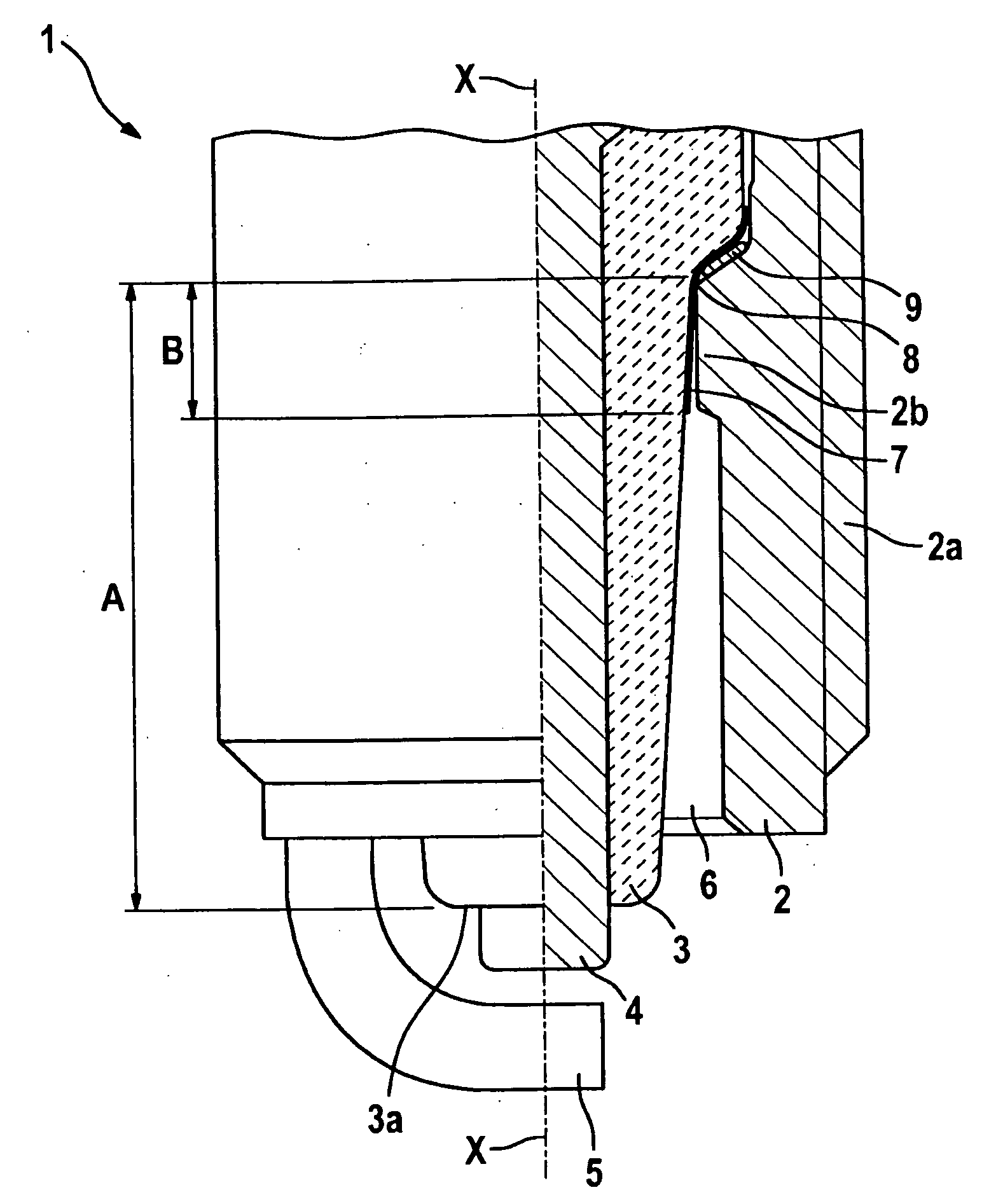
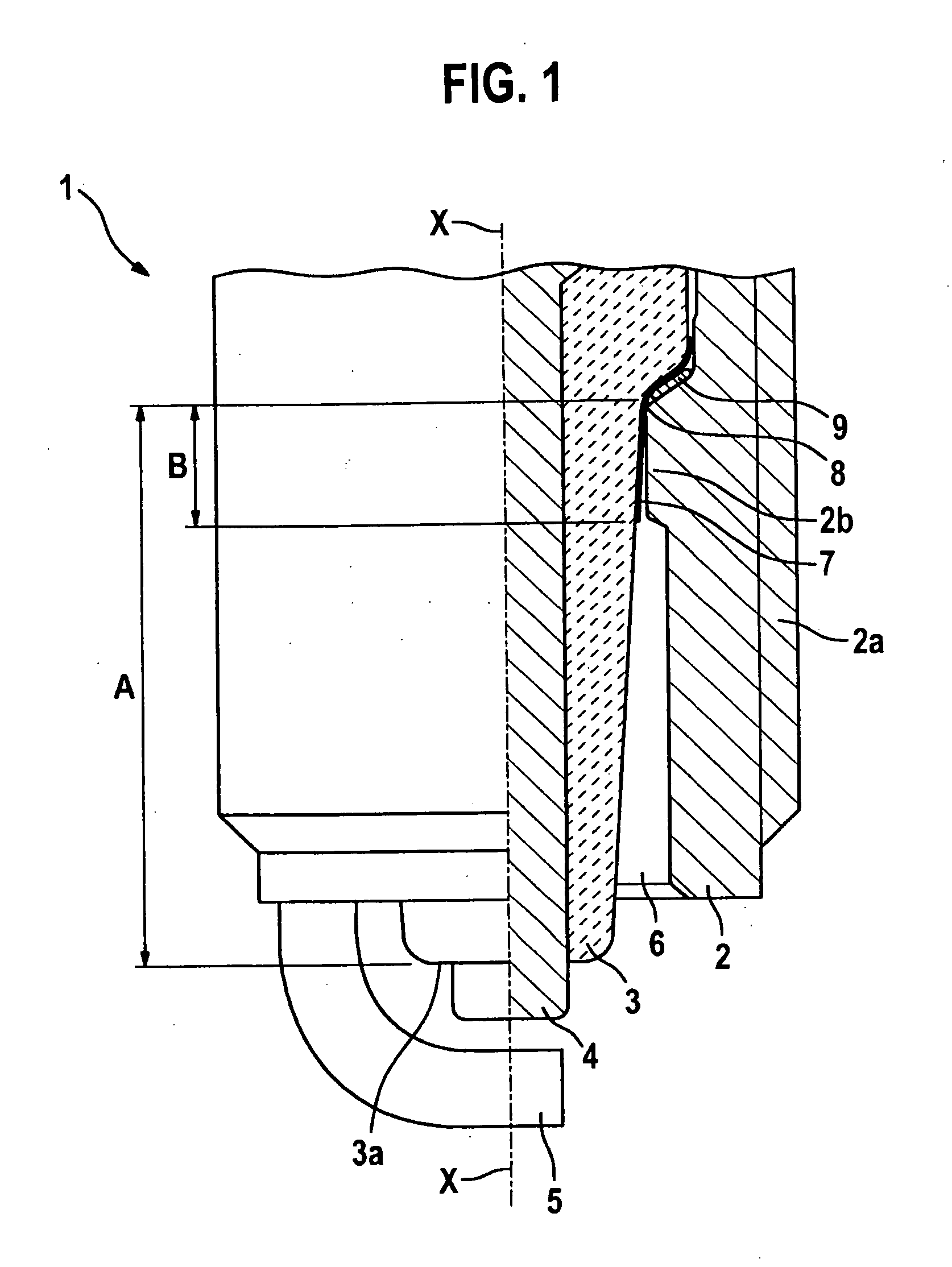
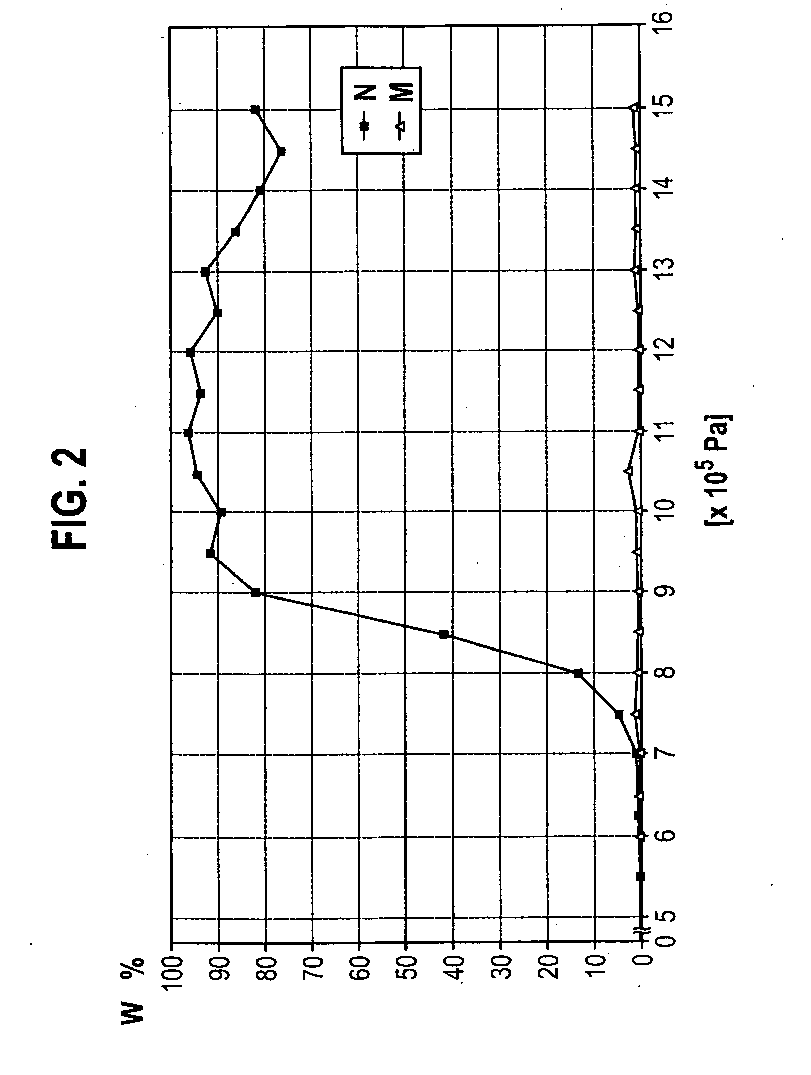
[0019]A spark plug 1 according to an exemplifying embodiment of the invention is described in detail below with reference to FIGS. 1 and 2.

[0020]As shown in FIG. 1, spark plug 1 encompasses a housing 2 that has an external thread 2a with which spark plug 1 is mounted on a component of an internal combustion engine. Spark plug 1 further encompasses an insulator 3 having an end surface 3a on the combustion-chamber side. Disposed in the interior of insulator 3 is a center electrode 4 that is disposed in the longitudinal direction X-X of the spark plug. A ground electrode 5 is connected to housing 2.

[0021]As is evident from FIG. 1, a breathing space 6 is constituted between insulator 3 and housing 2. Breathing space 6 is provided in annular fashion, and tapers from the electrode-side end of the spark plug. An internal circumferential land 2b is also configured on the inner side of housing 2. Land 2b has an annular shape, and a seal 9 is disposed between housing 2 and insulator 3 at a st...


PUM


Abstract

A spark plug has a center electrode disposed inside an insulator, and a housing that at least locally surrounds the insulator, and a conductive planar element that is electrically contacted to the housing is disposed on the insulator.

Description

BACKGROUND OF THE INVENTION[0001]1. Field of the Invention[0002]The present invention relates to a spark plug for internal combustion engines, e.g., for use in combustion chambers having a high pressure.[0003]2. Description of Related Art[0004]Spark plugs are known from the existing art in a variety of configurations. The known spark plugs have proven successful in principle for use in internal combustion engines. Very recently, however, the pressures in the combustion chamber at the moment of ignition have been constantly increasing, since the internal combustion engines are being more intensely turbocharged and operated with higher compression. Especially at high pressures, creepage sparks can occur upon ignition; these can also extend, in particular, into a breathing space of the spark plug that is formed, at the combustion-chamber end of the spark plug, between a tapering region of the insulator and a housing of the spark plug. In the homogeneous mode of the internal combustion ...

Claims


Application Information

Patent Timeline
IPC IPC(8): H01T13/20
CPCH01T13/38H01T13/36
Inventor KAISER, THOMASRICARDO, PAULO
Owner ROBERT BOSCH GMBH
Learn More