High definition lidar system

US20100020306A1Active Publication Date: 2010-01-28VELODYNE LIDAR USA INC

Image

  • High definition lidar system
  • High definition lidar system
  • High definition lidar system

Examples


Embodiment Construction

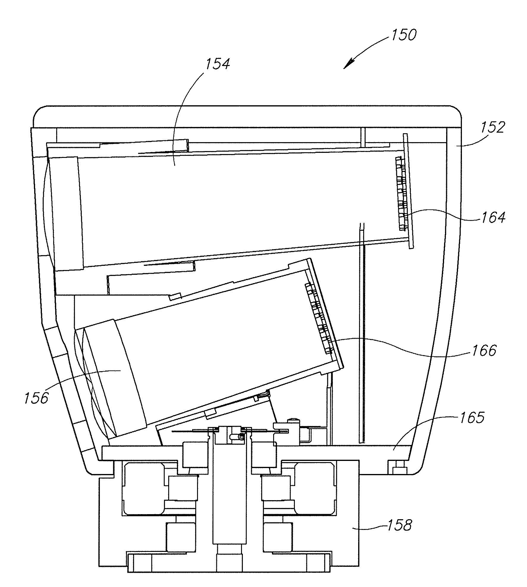
[0033]FIGS. 5-12 illustrate a Laser Imaging Detection and Ranging (Lidar) terrain mapping and obstacle detection system employed as an autonomous sensor for a vehicle. The Lidar system includes 8 assemblies of 8 lasers each as shown in FIG. 5 or 2 assemblies of 32 lasers each forming a 64-element Lidar system as shown in FIGS. 13-26. The system has a 360-degree horizontal field of view (FOV) and a 26.8-degree vertical FOV. The system is typically mounted on the top center of a vehicle, giving it a clear view in all directions, and rotates at a rate of up to 20 Hz, thereby providing a high point cloud refresh rate, such high rate being necessary for autonomous navigation at higher speeds. At this configuration, the system can collect approximately 1 million time of flight (TOF) distance points per second. The system provides the unique combination of 360 degree FOV, high point cloud density, and high refresh rate. The standard deviation of TOF measurements is equal to or less than 5 ...


PUM


Abstract

A lidar-based 3-D point cloud measuring system and method. An example system includes a base, a housing, a plurality of photon transmitters and photon detectors contained within the housing, a rotary motor that rotates the housing about the base, and a communication component that allows transmission of signals generated by the photon detectors to external components. The rotary component includes a rotary power coupling configured to provide power from an external source to the rotary motor, the photon transmitters, and the photon detectors. In another embodiment, the photon transmitters and detectors of each pair are held in a fixed relationship with each other. In yet another embodiment, a single detector is “shared” among several lasers by focusing several detection regions onto a single detector, or by using a single, large detector.

Description

PRIORITY CLAIM[0001]The application claims the benefit of U.S. Provisional Application Ser. No. 60 / 807,305 filed Jul. 13, 2006, the contents of which are hereby incorporated by reference.BACKGROUND OF THE INVENTION[0002]The use of a pulse of light to measure distance is well known. As is commonly used in devices such as a police speed detector, the basic concept is that of pulsing a laser emitter, which causes a burst of light to be emitted, usually focused through a lens or lens assembly. Then, the time it takes for that pulse of light to return to a detector mounted near the emitter is measured, and a distance can then be derived from that measurement with high accuracy.[0003]When multiple pulses are emitted in rapid succession, and the direction of those emissions is somehow sequentially varied, each distance measurement can be considered a pixel, and a collection of pixels emitted and captured in rapid succession (called a “point cloud”) can be rendered as an image or analyzed f...

Claims


Application Information

Patent Timeline
28 Jan 2010
Publication
US20100020306A1
IPC
G01C3/08
CPC
G01S7/4813; G01S7/4811; G01S17/89; G01S7/4817; H01S5/06216; H01S5/0428
Inventors
HALL, DAVID S.