
Floating solar energy conversion and storage apparatus

a technology of solar energy and storage apparatus, which is applied in the direction of machines/engines, propulsion parts, energy-based wastewater treatment, etc., can solve the problems that the above-described otec process has only limited success

Inactive Publication Date: 2010-02-04
HENDERSON RICHARD L
View PDF4 Cites 10 Cited by
  • Summary
  • Abstract
  • Description
  • Claims
  • Application Information

AI Technical Summary

Benefits of technology

[0005]The present invention is directed to an improved energy conversion and storage apparatus that floats on a body of water and confines and stores a large quantity of solar-heated water for producing electricity with a closed-cycle heat engine. The apparatus includes an expansive horizontal structure parallel to the surface of the water for storing one or more horizontal layers of water, a distributed array of solar collectors for gathering solar energy and imparting it to the stored water, and one or more closed-cycle heat engines for producing electricity utilizing the temperature differential between the stored water and ambient water at a moderate depth such as 30 m. When configured for use in fresh water, the solar collectors can be configured to transfer collected solar energy to the stored water using a convective process; and when configured for use in salt water, some or all of the solar collectors can be configured to transfer collected solar energy to the stored water using a distillation process that produces desalinated water as a by-product.

Problems solved by technology

In practice, the above-described OTEC processes have met with only limited success because of the relatively small naturally occurring temperature difference between warm surface water and cold deep water.

Method used


Image

  • Floating solar energy conversion and storage apparatus
  • Floating solar energy conversion and storage apparatus
  • Floating solar energy conversion and storage apparatus

Examples


Embodiment Construction

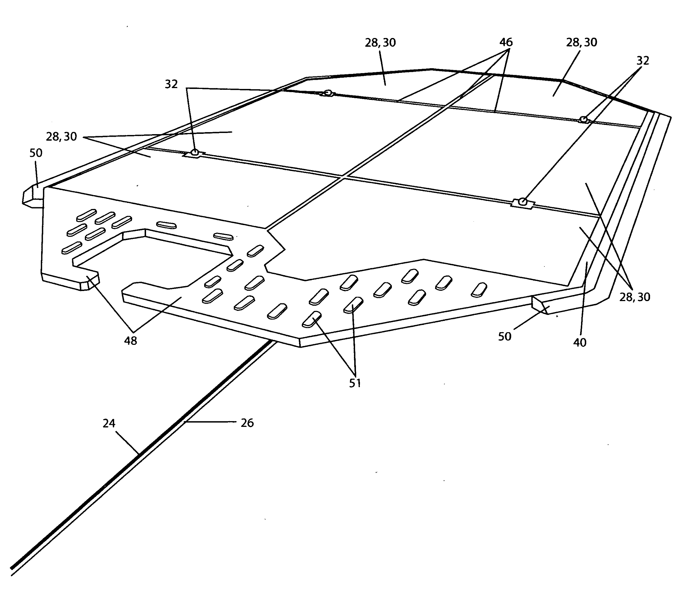
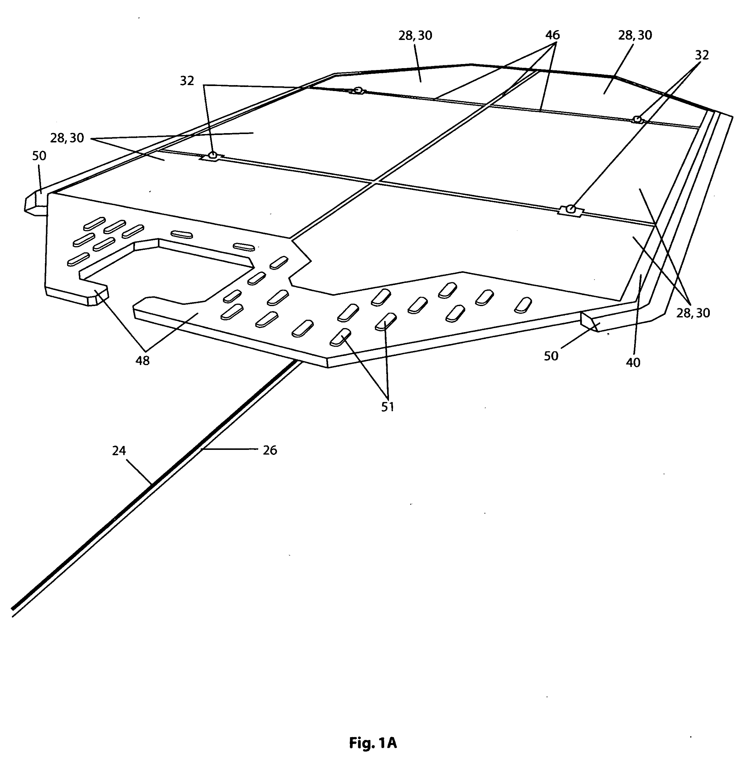
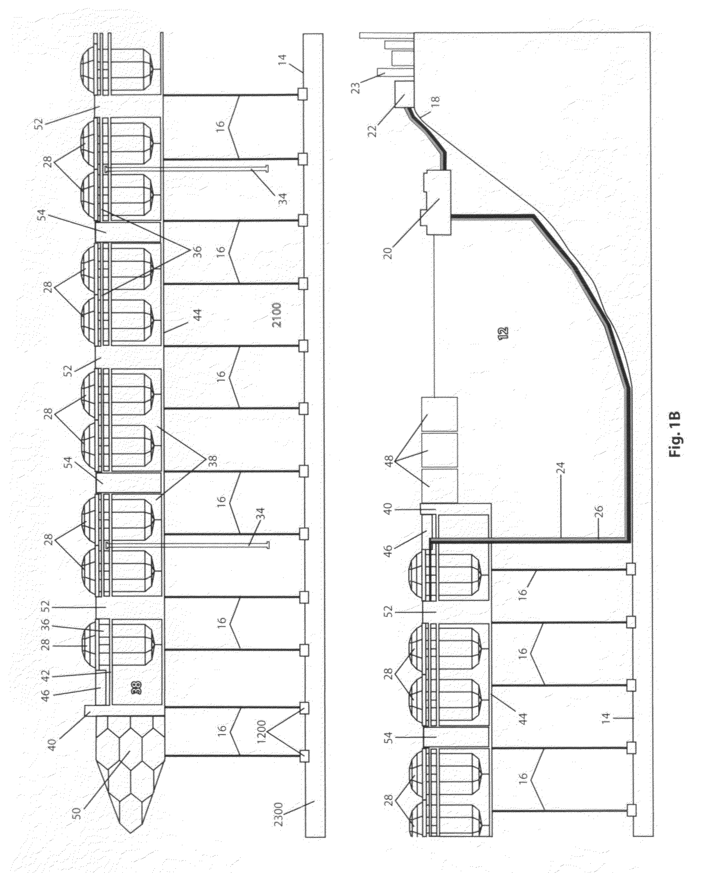
[0028]Referring to FIGS. 1A and 1B, the reference numeral 10 generally designates a floating solar energy conversion apparatus according to this invention, configured for off-shore use in a body of seawater 12. The apparatus 10 is anchored to the sea floor 14 by a distributed array of mooring cables 16. For example, the apparatus 10 may be floating in 100 m of seawater, several thousand meters from shore 18. The shore and near-shore facilities include a floating reservoir 20 for storing desalinated water, a pumping facility 22 for transferring desalinated water from reservoir 20 to a water distribution system, and an electricity transfer facility 23 for interfacing the apparatus 10 with a commercial electrical distribution system. Desalinated water produced by the apparatus 10 is transferred to reservoir 20 by a fresh water pipeline 24 extending downward to the seafloor 14, and following the contour of seafloor 14 as shown. And electricity produced by apparatus 10 is transferred to ...


PUM


Abstract

A solar energy conversion and storage apparatus floats on a body of water and confines and stores a large quantity of solar-heated water for producing electricity with a closed-cycle heat engine. An expansive horizontal structure parallel to the surface of the water confines one or more horizontal layers of water, a distributed array of heat transfer structures gathers solar energy and imparts it to the confined water, and one or more heat engines produce electricity utilizing the temperature differential between the confined water and ambient water. The heat transfer structures can be configured to transfer solar energy to the confined water using a convective process; and some or all of the heat transfer structures can be configured to transfer solar energy to the stored water using a distillation process that optionally produces distilled water as a by-product.

Description

RELATED APPLICATIONS[0001]This application claims the filing date of U.S. Provisional Patent Application Ser. No. 60 / 977,986, filed Oct. 5, 2007.BACKGROUND OF THE INVENTION[0002]The present invention relates to a floating solar energy conversion and storage apparatus.BACKGROUND OF THE INVENTION[0003]Scientists recognized long ago the possibility of converting heat energy stored in oceans and other large bodies of water into a more useful form of energy such as electricity. The well-known Ocean Thermal Energy Conversion (OTEC) process utilizes the characteristic difference in temperature (20° C.) between solar-warmed surface water and deep cold water to power a closed-cycle or open-cycle heat engine. The closed-cycle approach utilizes a liquid refrigerant or working fluid (ammonia, for example) having a low boiling point. The warm surface water is pumped through an evaporator to boil the refrigerant and produce vapor for driving a low-pressure turbine-generator; and the cold deep wat...

Claims


Application Information

Patent Timeline
Patent Type & Authority Applications(United States)
IPC IPC(8): B60L8/00
CPCB01D1/0035B01D5/0066C02F1/14Y02E10/47F24J2/5267Y02E10/46F24J2/345Y02W10/37Y02A20/212F24S60/30F24S20/70Y02T10/7072
Inventor HENDERSON, RICHARD L.
Owner HENDERSON RICHARD L
Learn More