Polymer nems for cell physiology and microfabricated cell positioning system for micro-biocalorimeter

a micro-biocalorimeter and cell technology, applied in the field of nanoscale electromechanical devices, can solve the problems of limiting the frequency achievable and the level of sensitivity attainable, and the standard approach used to make microelectromechanical systems (mems) cannot provide access to the nanoscale, so as to reduce the time and sample quantity, reduce the scale, and accelerate the parallel implementation of calorimetric measurement

Active Publication Date: 2010-02-04
CALIFORNIA INST OF TECH
View PDF15 Cites 48 Cited by
  • Summary
  • Abstract
  • Description
  • Claims
  • Application Information

AI Technical Summary

Benefits of technology

[0018]In addition, one or more embodiments of the invention provide calorimeter capable of detection of enthalpy change of chemical and biological reaction, such as enzyme activity and protein-ligand binding, in a 3.5 nanoliter (nL) volume. The calorimeter is embedded in parylene microfluidic system and can be coupled to other lab-on-a-chip microfluidic devices. Microfabrication of the calorimeter array and the accompanying microfluidic circuitry has enabled rapid and parallel implementation of calorimetric measurement. The reduction in scale also reduces the time and sample quantity required for such measurement. Sophisticated thermal insulation is engineered to maximize the measurement sensitivity. While a batch calorimeter is demonstrated, the calorimeter can be modified to perform isothermal titration, differential scanning and flow calorimetry.

Problems solved by technology

However, at microscale dimensions, there are limits with respect to the level of frequency achievable and the level of sensitivity attainable.
In this regard, the standard approaches used to make microelectromechanical systems (MEMS) cannot provide access to the nanoscale, where very large improvements in sensitivity can be attained [1].
A current barrier to their practical development and widespread use is the difficulty of achieving sensitive displacement transduction at the nanoscale.
This is not straightforward; approaches to displacement transduction commonly used for MEMS generally are not applicable to NEMS [8].
For example, the efficiency of capacitive detection precipitously decreases at the nanoscale, and the signal is typically overwhelmed by uncontrollable parasitic effects.
Existing prior art techniques used to measure forces exerted by biological structures have been primarily limited to optical measurements.
Furthermore, existing readouts for scanned probe microscopy cantilevers are predominantly based upon external (that is, off-chip) displacement sensing systems that, typically, greatly exceed the size scale of the cantilever sensors themselves.
In addition to the above, the ability to measure forces exerted by biological specimens have encountered significant limitations.
In such an environment, the amount of resolution attainable is limited.
Further, prior art techniques fail to provide an efficient mechanism to deliver individual cells to specific force sensors and fail to precisely control the chemical environment around a cell under study.
In addition, prior art delivery and control systems fail to maintain the viability of the biological sample under study while providing a mechanism to extract signals from a force sensor to a computer for readout and analysis.
However, measurement sensitivity of microfabricated calorimeters / thermometers fail to achieve the measurement sensitivity compatible to that of large scale calorimeters.
Such a lack of measurement sensitivity is determined by the sensitivity of the thermometer and capability to maximize the signal with good thermal isolation.
However, the prior art has failed to increase sensitivity to minimize the heat loss of the sample.

Method used


Image

  • Polymer nems for cell physiology and microfabricated cell positioning system for micro-biocalorimeter
  • Polymer nems for cell physiology and microfabricated cell positioning system for micro-biocalorimeter
  • Polymer nems for cell physiology and microfabricated cell positioning system for micro-biocalorimeter

Examples


Embodiment Construction

[0049]In the following description, reference is made to the accompanying drawings which form a part hereof, and which is shown, by way of illustration, several embodiments of the present invention. It is understood that other embodiments may be utilized and structural changes may be made without departing from the scope of the present invention.

Overview—Microfluidic Embedded Polymer NEMs Force Sensor

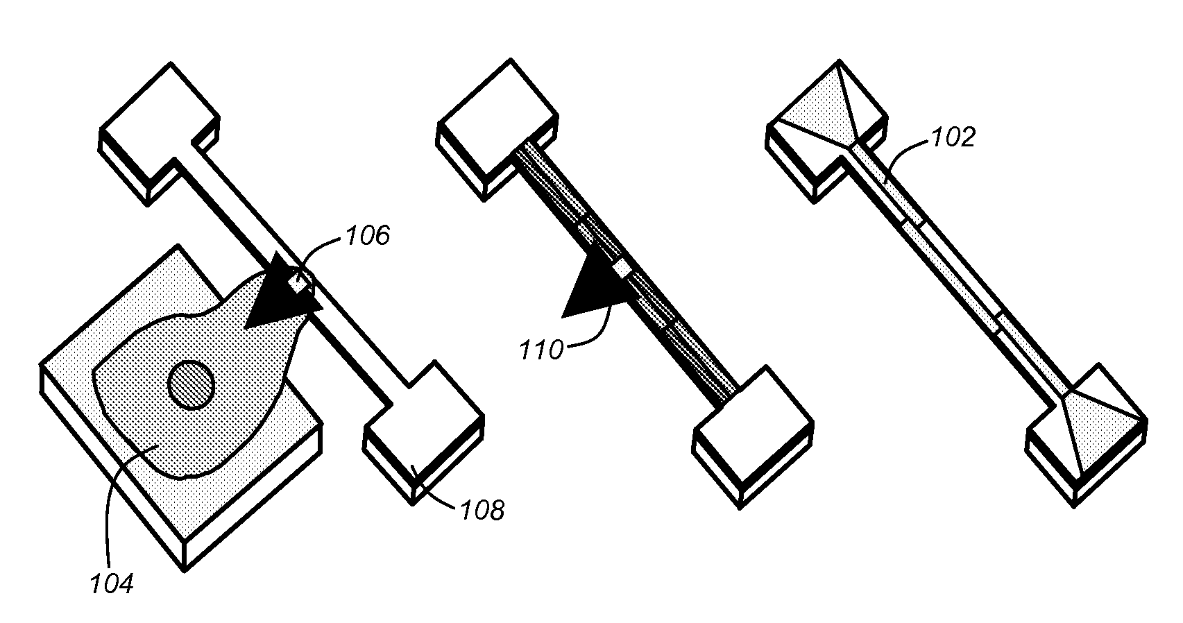
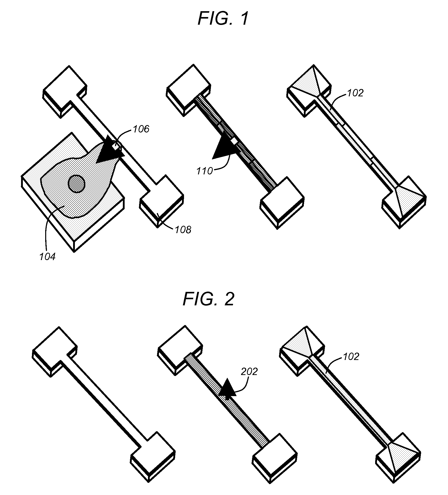
[0050]As described above, prior art techniques have attempted to measure the forces exerted by biological samples (e.g., single cells). In this regard, adherence cells (i.e., cells that adhere or have adhering properties with respect to adjacent surfaces), may exert forces when diffused across a surface. Prior art mechanisms attempted to measure such forces primarily utilizing optical means. In this regard, prior art mechanisms were based on optical measurements of deflected substrates or members. For example, cells (e.g., monocyte or macrophage cells), may be placed superior to polydim...


PUM

PropertyMeasurementUnit
time-constantaaaaaaaaaa
frequencyaaaaaaaaaa
widthsaaaaaaaaaa

Abstract

A microfluidic embedded nanoelectromechanical system (NEMs) force sensor provides an electrical readout. The force sensor contains a deformable member that is integrated with a strain sensor. The strain sensor converts a deformation of the deformable member into an electrical signal. A microfluidic channel encapsulates the force sensor, controls a fluidic environment around the force sensor, and improves the read out. In addition, a microfluidic embedded vacuum insulated biocalorimeter is provided. A calorimeter chamber contains a parylene membrane. Both sides of the chamber are under vacuum during measurement of a sample. A microfluidic cannel (built from parylene) is used to deliver a sample to the chamber. A thermopile, used as a thermometer is located between two layers of parylene.

Description

CROSS-REFERENCE TO RELATED APPLICATIONS[0001]This application claims the benefit under 35 U.S.C. Section 119(e) of the following co-pending and commonly-assigned U.S. provisional patent application(s), which is / are incorporated by reference herein:[0002]Provisional Application Ser. No. 60 / 834,253, filed on Jul. 28, 2006, by Michael L. Roukes, Chung-Wah Fon, Wonhee Lee, and Hongxing Tang, entitled “Vacuum-insulating polymer-based micro-biocalorimeter integrated with microfluidics” attorneys' docket number 176.34-US-P 1 (CIT-4697-P);[0003]Provisional Application Ser. No. 60 / 834,052, filed on Jul. 28, 2006, by Blake W. Axelrod, Michael L. Roukes, and John Tan, entitled “Plastic NEMs for cell physiology” attorneys' docket number 176.34-US-P2 (CIT-4698-P); and[0004]Provisional Application Ser. No. 60 / 834,288, filed on Jul. 28, 2006, by Blake W. Axelrod, Michael L. Roukes, and John Tan, entitled “Microfabricated cell positioning system” attorneys' docket number 176.34-US-P3 (CIT-4699-P);S...

Claims


Application Information

Patent Timeline
Patent Type & Authority Applications(United States)
IPC IPC(8): G01L1/18B44C1/22
CPCB82Y35/00G01L1/044G01N33/5026G01N33/5029Y10S977/956G01N33/54373Y10S977/958Y10S977/724G01N33/5032
Inventor ROUKES, MICHAEL L.FON, CHUNG-WAHLEE, WONHEETANG, HONGXINGAXELROD, BLAKE WATERSTAN, JOHN LIANG
Owner CALIFORNIA INST OF TECH
Why Eureka
Try Eureka