
Apparatus and method for sputtering target debris reduction

a technology of apparatus and debris, applied in the field of sputtering targets, can solve the problems of nicrox debris that eventually flakes off the surface, the creation of sputtered regions and non-sputtered regions on sputtering targets, etc., to achieve the effect of reducing an amount of debris and facilitating the sputtering coating of the articl

Inactive Publication Date: 2010-02-04
GUARDIAN GLASS LLC
View PDF16 Cites 6 Cited by
  • Summary
  • Abstract
  • Description
  • Claims
  • Application Information

AI Technical Summary

Benefits of technology

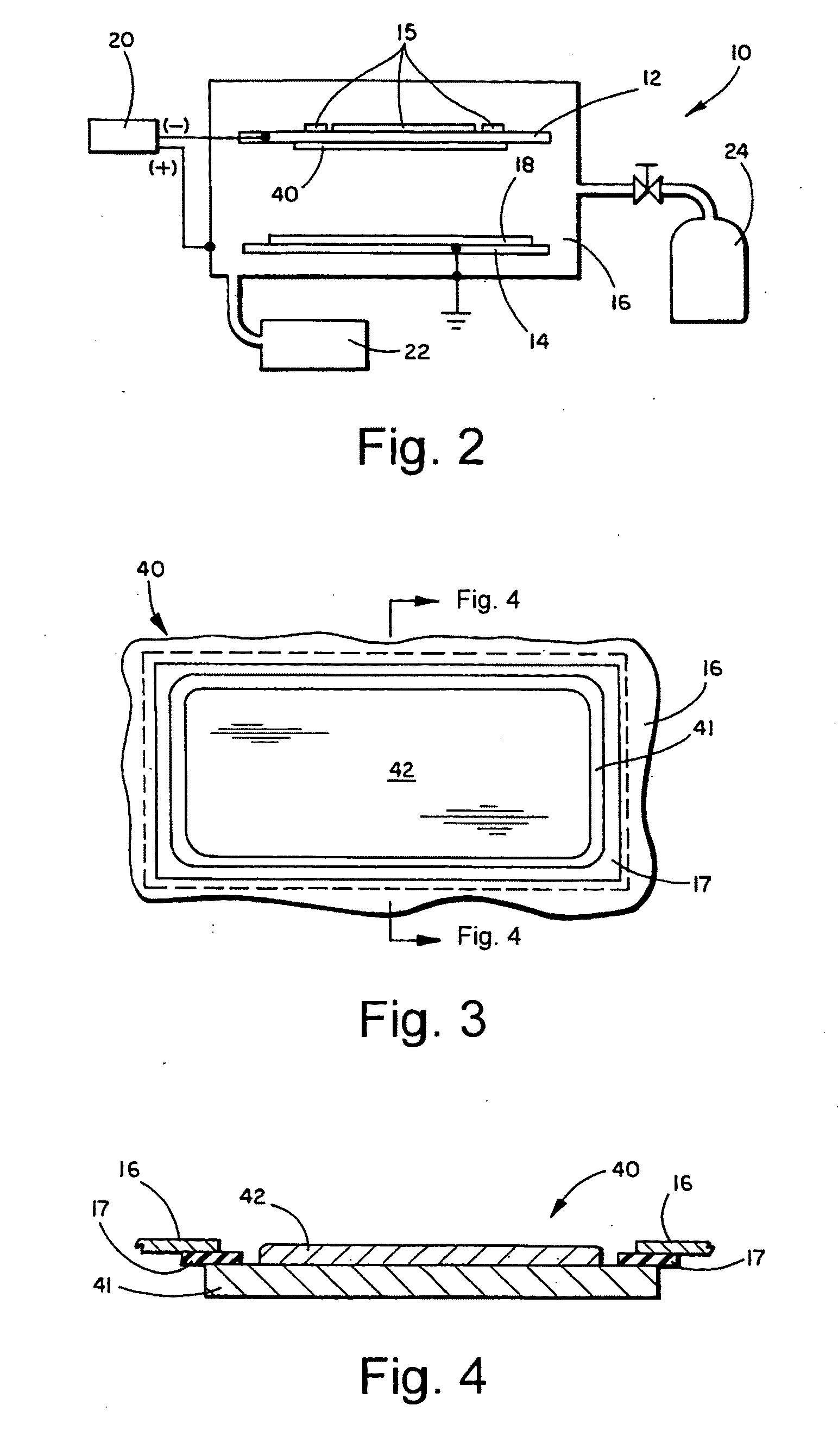
[0004]One known technique for enhancing conventional sputtering processes involves arranging magnets behind or near the target to influence the path taken by electrons within the sputtering chamber, thereby increasing the frequency of collisions with sputtering gas atoms or molecules. Additional collisions create additional ions, thus further sustaining the sputtering gas plasma. An apparatus utilizing this enhanced form of sputtering by means of strategically located magnets generally is referred to as a magnetron system.
[0012]In certain example embodiments, a method for reducing an amount of debris created during sputtering is provided. There is provided a magnetron sputtering apparatus configured to generate a reactive environment used in sputter coating an article, the magnetron sputtering apparatus comprising a vacuum chamber, one or more magnets arranged to facilitate the sputter coating of the article, a sputtering target having target material located thereon and being located in the vacuum chamber. An encapsulating coating is formed, directly or indirectly, on the target material at one or more first areas thereof where the target material substantially is not used in the sputter coating of the article. The encapsulating coating substantially isolates the target material at the one or more first areas from the reactive environment of the sputtering apparatus.
[0013]In certain example embodiments, a magnetron sputtering apparatus for sputter coating an article in an oxidizing environment is provided. A vacuum chamber is provided. One or more magnets are arranged to facilitate the sputter coating of the article. A DC planar sputtering target is located in the vacuum chamber. The sputtering target has a target material located thereon. A cathode is connected to the sputtering target. An encapsulating coating is formed, directly or indirectly, on the target material at one or more first areas thereof where the target material substantially is not used in the sputter coating of the article. The encapsulating coating substantially isolates the target material at the one or more first areas from the oxidizing environment of the sputtering apparatus. The encapsulating coating includes inorganic materials or materials that resist decomposition in the oxidizing environment, and is substantially electrically non-conductive. The encapsulating coating is formed on the target material such that at least some of the target material is exposed to the oxidizing environment in a racetrack-like shape of the target material that corresponds to at least a second area of the target material where the target material substantially is used in the sputter coating of the article. The encapsulating coating reduces an amount of debris that otherwise would be formed by oxidation of the target material in the one or more first areas by at least about 50%.

Problems solved by technology

Unfortunately, conventional sputtering techniques suffer from several disadvantages.
For example, one drawback of conventional sputtering techniques relates to the creation of sputtered regions and non-sputtered regions on sputtering targets.
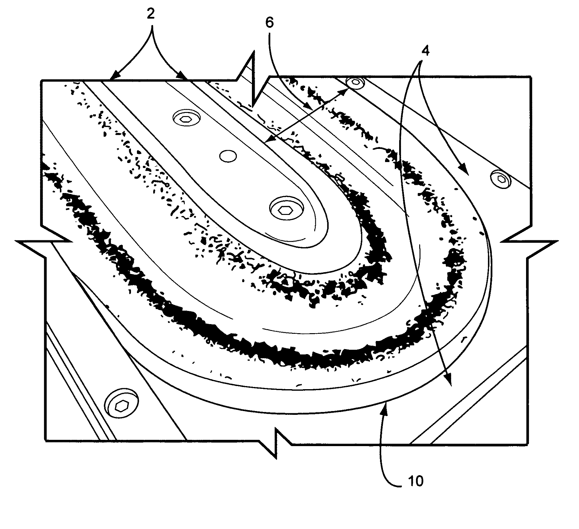
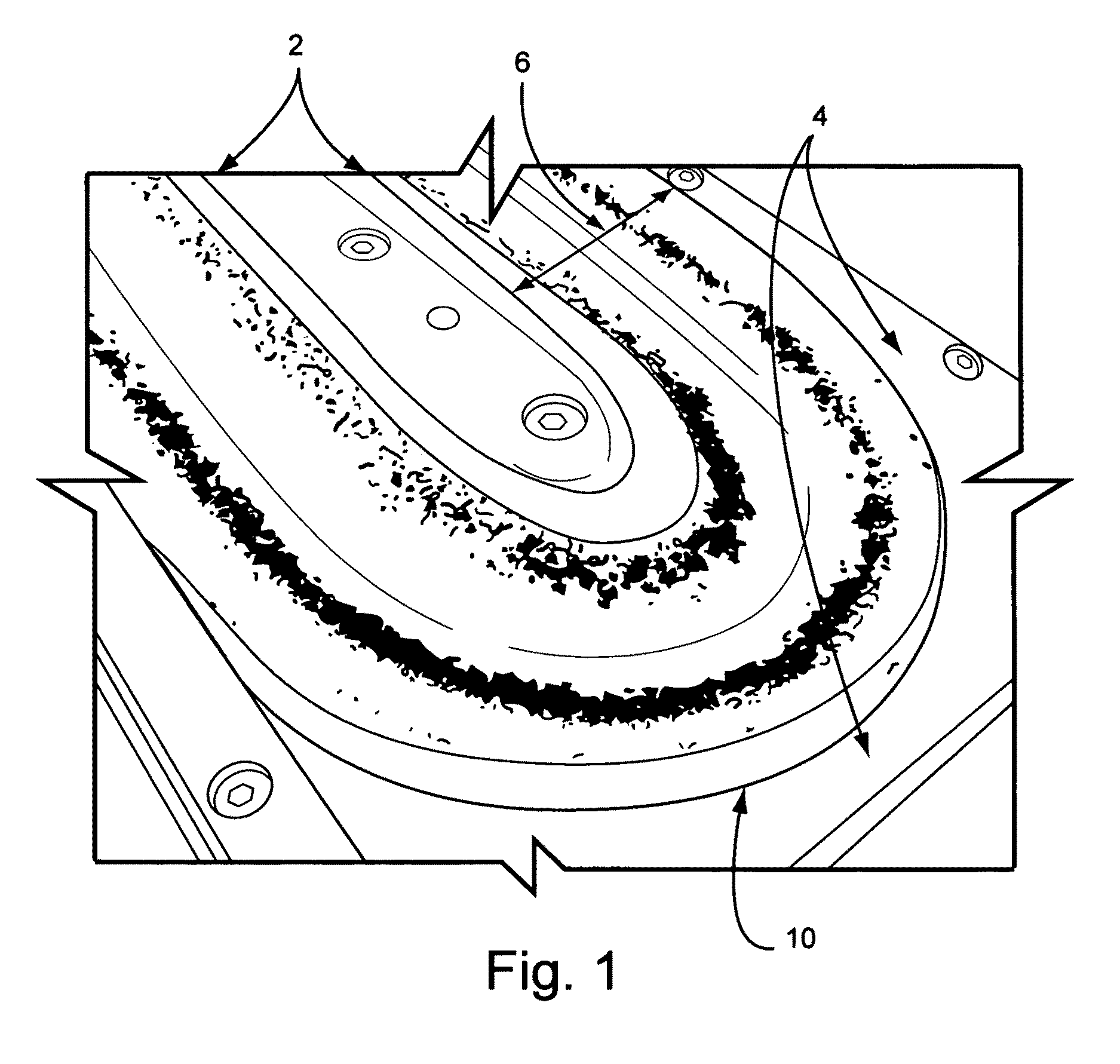
This surface oxidation leads to a build-up of NiCrOx debris that eventually flakes off of the surface and falls onto the chamber floor and / or onto the product being coated.
However, areas that are not a part of the racetrack (but are inside of the highly oxidizing plasma) are left to oxidize substantially continuously throughout the production campaign.
Unfortunately, such current techniques require the sputtering campaign to be at least temporarily halted, thereby taking up time and costing money.
In addition, such techniques involve an approach that reacts to a problem rather than an approach that reduces the likelihood of the problem from occurring in the first place.

Method used


Image

  • Apparatus and method for sputtering target debris reduction
  • Apparatus and method for sputtering target debris reduction
  • Apparatus and method for sputtering target debris reduction

Examples


example

[0036]To test the feasibility of an oxidation barrier based on a sol-gel coating in connection with a nichrome target, the following test was devised. Three sample specimens were prepared. First, a silicon oxide inclusive sol-gel was applied in liquid form to a U.S. Mint quarter via a spray bottle. The sprayed quarter was allowed to dry, and it was green cured in a box furnace for approximately 10 minutes at about 200 degrees C. Second, a silicon oxide inclusive sol-gel was applied in liquid form to a U.S. Mint quarter via a spray bottle. This second sprayed quarter was allowed to dry, but it was not cured. Third, a U.S. Mint quarter was not treated with a sol-gel solution. As is known, U.S. Mint quarters currently have an outer cladding comprising about 25% nickel and 75% copper. An air atmosphere belt furnace was set to bake for about 30 minutes at about 625 degrees C. to simulate the harsh oxidizing environment of a sputtering apparatus.

[0037]The test results for the three sample...


PUM

PropertyMeasurementUnit
Fractionaaaaaaaaaa
Temperatureaaaaaaaaaa
Shapeaaaaaaaaaa

Abstract

Certain example embodiments relate to techniques for reducing the amount of debris being formed on the surface of planar sputtering targets. More particularly, a coating may be applied to the sputtering material in areas where sputtering substantially does not occur (typically inside and outside of a racetrack) in certain example embodiments. The coating optionally may be cured. In certain example embodiments, the coating may be include inorganic materials or materials that resist decomposition in a severely oxidizing environment, and / or are electrically non-conductive materials. For example, the coating may be a cured-form sol-gel comprising, for example, silicon oxide, titanium oxide, and / or the like. The coating substantially encapsulates the target material where sputtering substantially does not occur, thus reducing the amount of debris that is created during sputter coating.

Description

FIELD OF THE INVENTION[0001]Certain example embodiments of this invention relate to sputtering targets. More particularly, certain example embodiments of this invention relate to techniques for reducing the amount of debris being formed on the surface of planar sputtering targets. In certain example embodiments, a coating (e.g., a sol-gel based coating) is applied to areas of planar targets that are subject to substantially uninterrupted surface oxidation (e.g., inside or outside of the “racetrack” of sputtering targets) and then cured to substantially encapsulate such areas, thereby reducing the likelihood of oxidation occurring on or proximate to such encapsulated areas and thus also reducing the amount of debris that otherwise would be formed by such oxidation. In certain example embodiments, the coating may include silicon oxide, titanium oxide, and / or the like.BACKGROUND AND SUMMARY OF EXAMPLE EMBODIMENTS OF THE INVENTION[0002]The use of sputtering in order to deposit coatings ...

Claims


Application Information

Patent Timeline
IPC IPC(8): C23C14/35
CPCC23C14/3414H01J37/3447H01J37/3429H01J37/3408
Inventor MILLER, GREG
Owner GUARDIAN GLASS LLC
Learn More