Transparent material processing with an ultrashort pulse laser

a technology of ultrashort pulse laser and transparent material, which is applied in the direction of thermography, glass making apparatus, manufacturing tools, etc., can solve the problems of poor cleaving process precision, low quality of cleaving facets, and additional interaction, so as to improve material processing results and improve processing speed

Inactive Publication Date: 2010-02-04
IMRA AMERICA
View PDF101 Cites 296 Cited by
  • Summary
  • Abstract
  • Description
  • Claims
  • Application Information

AI Technical Summary

Benefits of technology

[0036]During the cleaving process of a scribed material, the fracture begins at the surface scribe feature and propagates down through the material. If the surface groove is too shallow, the fracture will tend to wander, resulting in low quality cleave facets and poor cleave process precision. With the presence of additional scribe feature(s) within the bulk of the material, however, the fracture is guided through the material in the desired direction, resulting in higher cleaving precision and facet quality than would be expected for the case of a shallow surface scribe only.
[0064]Various embodiments improve processing speed relative to that obtainable with a single beam and multiple processing passes with different beam focal positions, and may improve material processing results.

Problems solved by technology

The high repetition rate of the laser and significant pulse-to-pulse overlap results in an additional interaction between the material modification created by the previous laser exposure and the subsequent pulses in the same region.
If the surface groove is too shallow, the fracture will tend to wander, resulting in low quality cleave facets and poor cleave process precision.

Method used


Image

  • Transparent material processing with an ultrashort pulse laser
  • Transparent material processing with an ultrashort pulse laser
  • Transparent material processing with an ultrashort pulse laser

Examples


Embodiment Construction

1. Ultrashort Pulse Laser Scribing

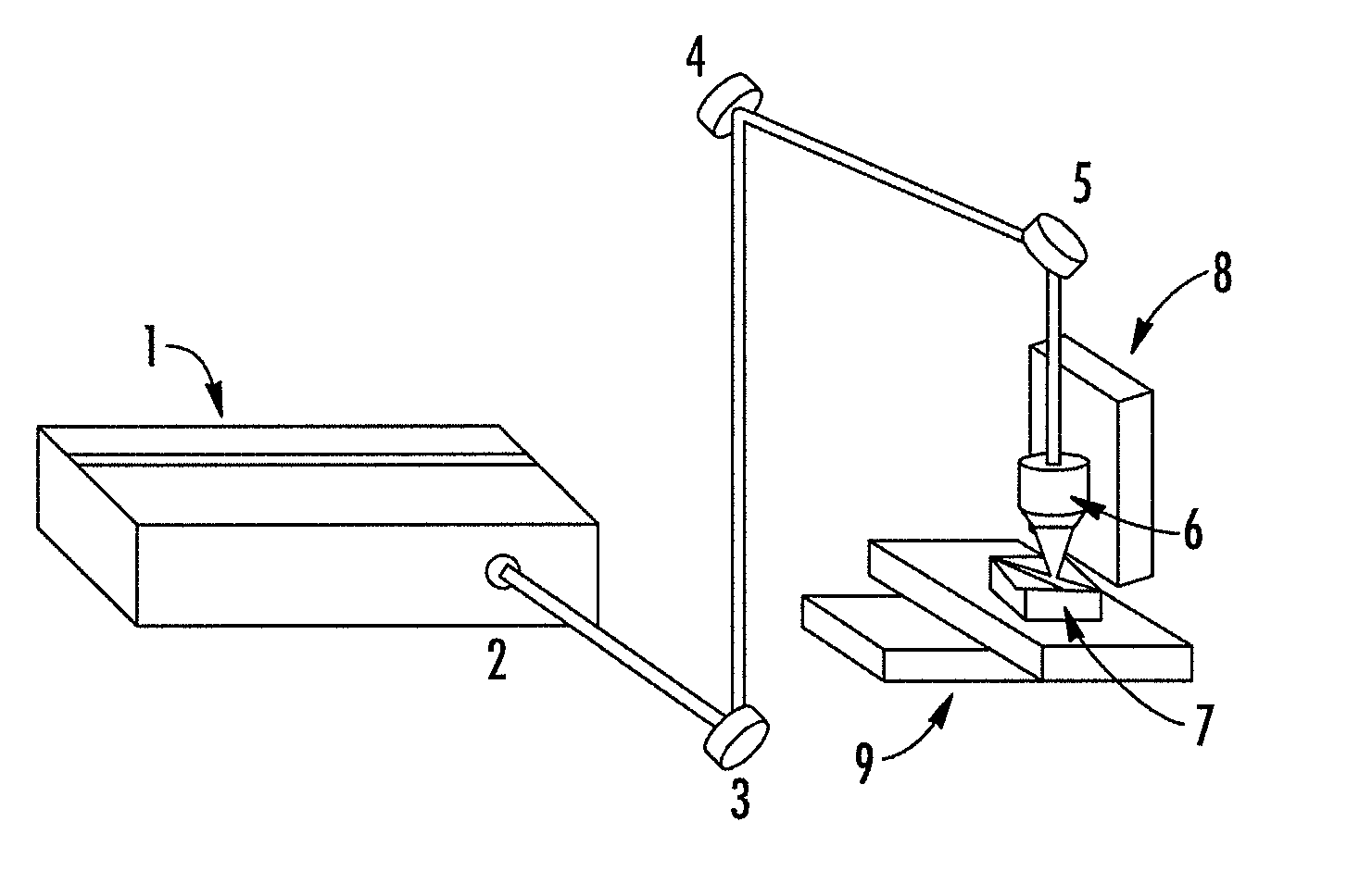
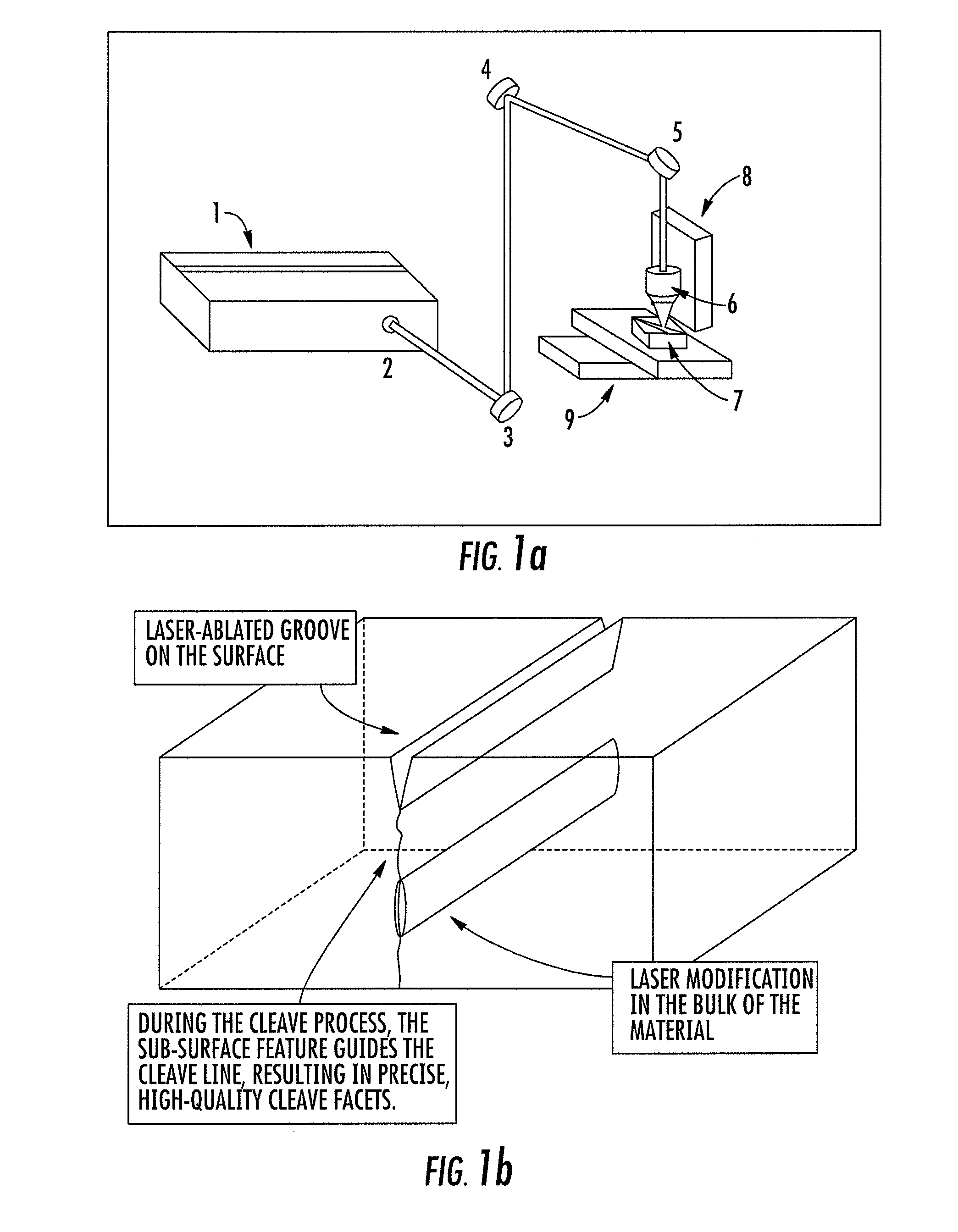
[0092]FIG. 1 illustrates one embodiment of the current invention, which is a method for scribing transparent materials for subsequent cleaving. This embodiment employs a laser system (1) producing a beam of ultrashort laser pulses (2), an optical system (6) that generates a desired laser beam intensity distribution, and a target material (7) to be scribed that is transparent to the wavelength of the laser pulses. In addition, a Z-axis stage (8) is used for beam focus position control (depth), and an automated X-Y axis stage assembly (9) is generally required for moving the work pieces (7) laterally relative to the focused laser beam. Alternatively, the laser beam (2) could be moved relative to a stationary target material with the use of scanning mirrors (3), (4), and (5).

[0093]The laser beam (2) is directed through the optical system (6), which transforms the laser beam (2) to create a desired 3-dimensional intensity distribution. Particular region...


PUM

PropertyMeasurementUnit
total energyaaaaaaaaaa
speedaaaaaaaaaa
melting temperatureaaaaaaaaaa

Abstract

Methods, devices, and systems for ultrashort pulse laser processing of optically transparent materials are disclosed, with example applications in scribing, marking, welding, and joining. For example, ultrashort laser pulses create scribe features with one pass of the laser beam across the material, with at least one of the scribe features being formed below the surface of the material. Slightly modifying the ultrashort pulse laser processing conditions produces sub-surface marks. When properly arranged, these marks are clearly visible with correctly aligned illumination. Reflective marks may also be formed with control of laser parameters. A transparent material other than glass may be utilized. A method for welding transparent materials uses ultrashort laser pulses to create a bond through localized heating. In some embodiments of transparent material processing, a multifocus beam generator simultaneously forms multiple beam waists spaced depthwise relative to the transparent material, thereby increasing processing speed.

Description

CROSS REFERENCE TO RELATED APPLICATIONS[0001]This application claims priority to U.S. Ser. No. 61 / 064,476, filed Mar. 7, 2008, entitled “Transparent material processing with an ultrashort pulse laser”. This application claims priority to U.S. Ser. No. 61 / 146,536, filed Jan. 22, 2009, entitled “Transparent material processing with an ultrashort pulse laser”. The disclosures of Ser. No. 61 / 064,476 and Ser. No. 61 / 146,536 are hereby incorporated by reference in their entirety. This application is related to U.S. Ser. No. 11 / 517,325, entitled “Transparent material processing with an ultrashort pulse laser”, filed Sep. 8, 2006, which claims priority to U.S. Ser. No. 60 / 714,863 filed Sep. 8, 2005. The disclosures of both Ser. No. 11 / 575,235 and Ser. No. 60 / 714,863 are hereby incorporated by reference in their entirety. The disclosure of Ser. No. 11 / 517,325 is published as U.S. patent application publication, Pub. No. 20070051706, published Mar. 8, 2007. The above applications are assigned...

Claims


Application Information

Patent Timeline
Patent Type & Authority Applications(United States)
IPC IPC(8): B23K26/06B23K26/00B23K26/38
CPCB23K26/0635B29C66/952B28D5/00B28D5/0011B29C65/1606B29C65/1612B29C65/1619B29C65/1638B29C65/1658B29C65/1687B29C65/38B29C66/1122B29C66/43B29C66/73366B29K2995/0026B29C65/1629B29C65/1635B29C65/1654B29C66/836B23K26/4075B23K26/40B29C66/71B29C66/73161B29C66/73921B41M5/26B41M5/262B41M5/267B23K26/0624B23K2103/50B23K2103/54B29K2069/00H01L21/0275B23K26/0676B23K26/083B23K26/0869B23K26/324B23K26/402B23K26/21B23K26/359B23K26/364B23K26/53B23K26/55C03B23/006C03B33/102C03C23/0025H01L21/268H01L21/78
Inventor ARAI, ALAN Y.CHO, GYU C.XU, JINGZHOUYOSHINO, FUMIYOZHANG, HAIBINBOVATSEK, JAMESYOSHIDA, MAKOTO
Owner IMRA AMERICA
Why Eureka
Try Eureka