
Security label laminate and method of labeling

Active Publication Date: 2010-02-04
AUTHENTIX INC
View PDF2 Cites 48 Cited by
  • Summary
  • Abstract
  • Description
  • Claims
  • Application Information

AI Technical Summary

Benefits of technology

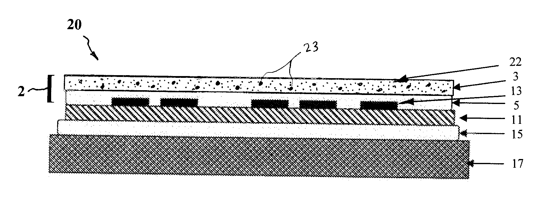
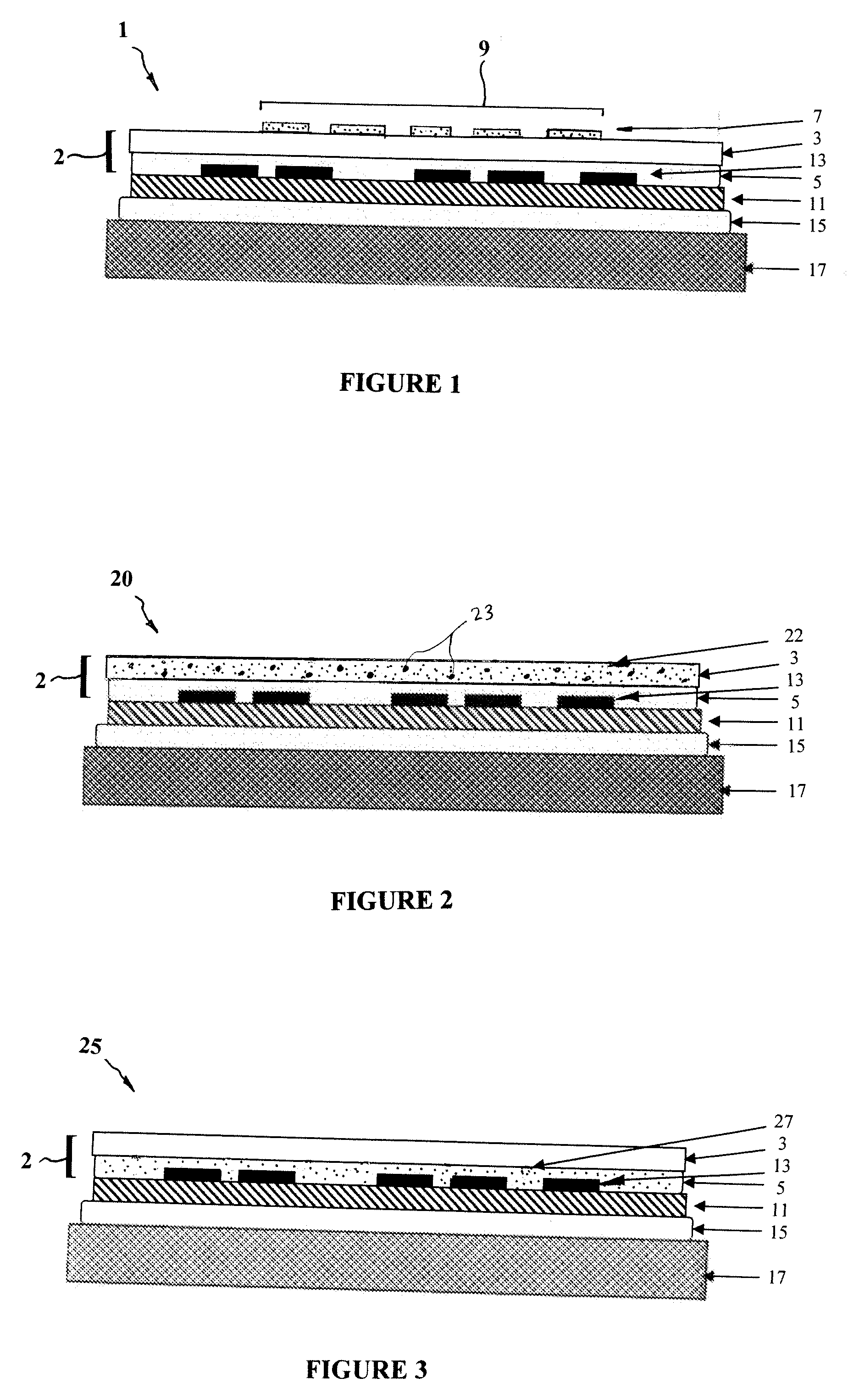
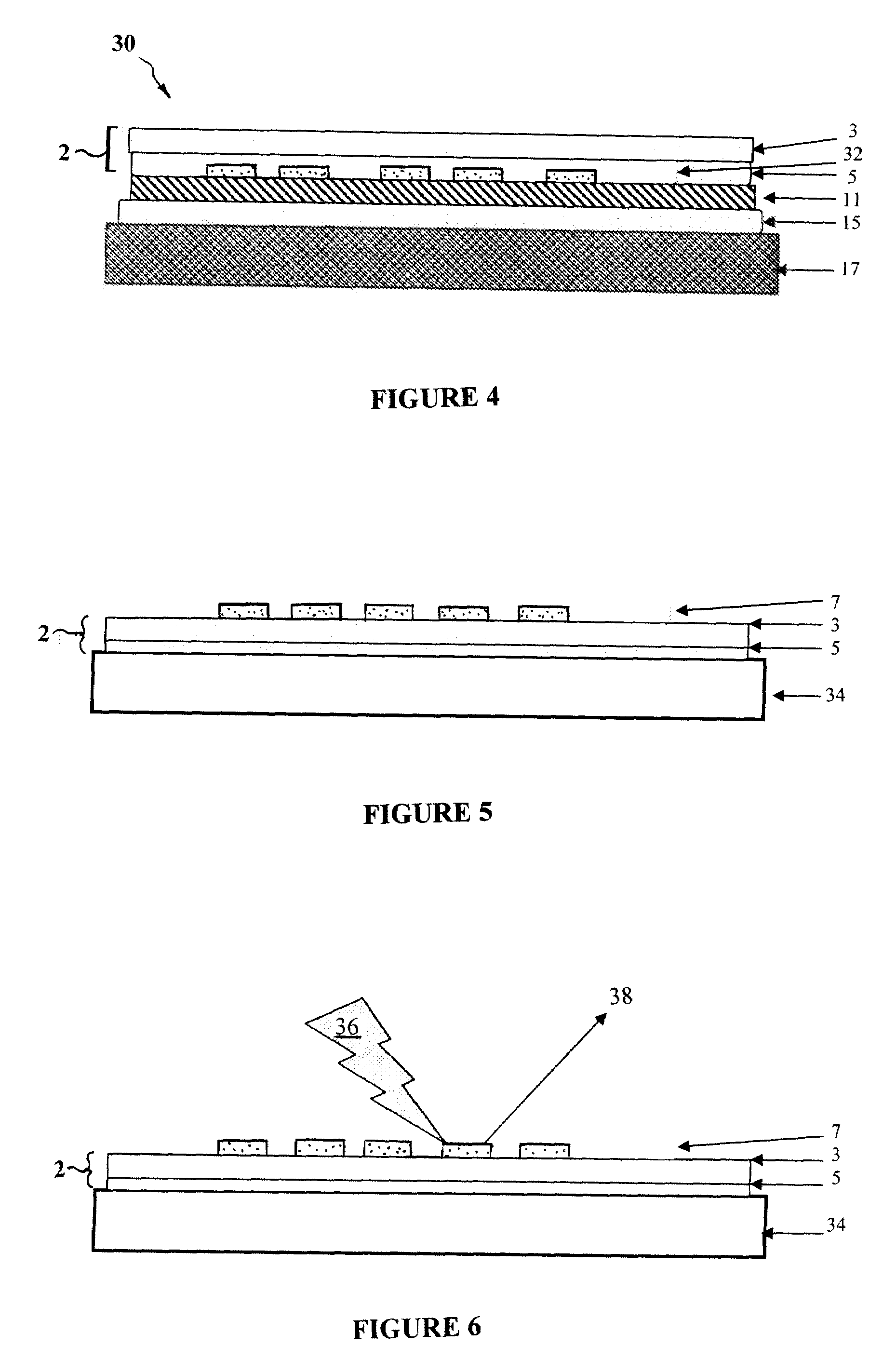
[0007]The invention is an improved label and labeling method that substantially reduces the amount of marker material necessary to reliably store and relay invisible product data. To this end, the label of the invention comprises a laminate that includes a light transmissive layer of sheet material, a light transmissive layer of adhesive that detachably affixes the sheet material over the surface of a product, a product package or a label substrate, and an amount of invisible marker incorporated into the sheet material or adhesive that contains invisible information detectable by light having a selected wavelength. The amount of marker selected is sufficient to allow information in the marker to be detected only when the laminate is affixed over a surface that provides a selected optical background that maximizes the detectability of the marker. In the preferred embodiment, the selected background is a white background. The ability of the label laminate to be removed from the surface of a product, a product package or a label substrate and positioned over such a background eliminates the optical interference associated with most backgrounds and greatly reduces the amount of marker material required for reliable detection a reading. For example, in contrast to the 5 weight percent quantities of marker material used in the prior art, the label laminate of the invention requires a quantity of marker material of only between about 0.01 and 0.001 percent by weight or less.
[0011]The marker may be a fluorescent or phosphorescent material, and the selected wavelength that the marker is exposed to may be the excitation wavelength of the fluorescent or phosphorescent material. The selected excitation wavelength may be within the ultraviolet, visible or infrared range. While the light emitted by the fluorescent or phosphorescent marker material will be a different wavelength than the excitation wavelength, the emitted light may also be within the ultraviolet, visible or infrared range. When the emitted light is in the visible range of wavelengths, the detection of the information incorporated in the marker may be readable by the unaided human eye or it may be machine-readable. The marker may also be a material that absorbs an ultraviolet or infrared wavelength, and the selected wavelength may be the wavelength that is absorbed by the marker. In such an embodiment, detection of the information would be by a reading device capable of “seeing” the dark patterns generated when the marker was exposed to the absorbed ultraviolet or infrared wavelength. Two or more markers with different excitation or absorption wavelength properties may be incorporated, imbedded, or printed onto one of the label laminate components to render counterfeiting of the label laminate more difficult.

Problems solved by technology

For example, the data in invisible, optically detected markers cannot be reliably detected or read when printed or placed over black text because of the black text's light absorption at ultraviolet, visible and infrared wavelengths.
Reliable detection and reading of such data over specularly reflective backgrounds, such as silver foil, is similarly difficult because of light scattering.
Detection over colored backgrounds is problematical because of the absorption of various wavelengths.
However, such a solution is expensive, as marker materials (which are often formed from rare earth metals) typically cost about between $1 and $10 / gram.
Since such prior art labels already require the invisible marker material to constitute as much as 5% of the weight of the label component that they are imbedded in, further increases in the use of such an expensive material is undesirable.
Moreover, any substantial increase in the proportion of such marker material compromises the invisibility of the marker and / or detectability of the marker by non-optical means and can also adversely change the physical characteristics of the material that it is imbedded in.
In addition, the final label / laminate system with high security marker concentrations may appear cloudy or stained depending on the marker and technique employed.
Detection and ultimately unauthorized replication (counterfeit) risks increase with high marker loads.

Method used


Image

  • Security label laminate and method of labeling
  • Security label laminate and method of labeling
  • Security label laminate and method of labeling

Examples


example 1

[0039]Thermal transfer ribbon is prepared with a UV excitable material, UVXPBR. This particular material has the property of emitting red visible light after excitation with UV light, as described at www.maxmax.com. The UVXPBR is mixed with a clear resin (15% resin, 85% solvent, primary component 2-butanone) at a concentration of 1000 parts per million (ppm). This is accomplished by dissolving 0.03 g UVXPBR in 30 g resin solvent mixture and stirring to solution at room temperature. The resulting clear solution is hand coated on pre-slit 4″ wide thermal transfer ribbon with a number 4 Mier rod. Coated thickness after solvent evaporation is about 1 micron and the marker content in the resin is about 6667 ppm. Several hand coatings are completed in series and the ribbon is wound, coated side out, on a new 1″ core.

[0040]The freshly prepared ribbon was threaded onto a Zebra model ZM400 thermal transfer printer. Along with this ribbon, 1″ round clear label laminates 2 produced by laminati...

example 2

[0049]A thermal transfer ribbon is prepared with A-225 up-converting IR excitable material available from Epolin, Inc. This particular material has the property of emitting green visible light after excitation with IR light, as described at www.epolin.com. The A-225 material is mixed with a clear resin (15% resin, 85% solvent, primary component 2-butanone) at a concentration of 1000 ppm. This is accomplished by mixing 0.03 g A-225 with 30 g resin solvent mixture and vigorously stirring to dispersion at room temperature. The resulting mixture is hand coated on pre-slit 4″ wide thermal transfer ribbon with a number 4 Mier rod. Coated thickness after solvent evaporation is about 1 micron and the marker content in the resin is about 6667 ppm. Several hand coatings are completed in series and the ribbon is wound, coated side out, on a new 1″ core. The freshly prepared ribbon is threaded onto a Zebra model ZM400 thermal transfer printer. Along with this ribbon, 1″ round clear labels, prod...

example 3

[0052]In this example, an IR absorbing dye was dissolved in 2-butanone, then mixed into a removable acrylic adhesive mixture at a concentration of 5000 ppm. The dye used was FHI9072, described on www.fabricolorholding.com. The adhesive mixture was coated on 2-mil polyester film to a thickness of 1 mil., thus forming the adhesive layer 5 of a label laminate 2. This resulted in a marker concentration of 12.5 microgram / cm2. The resulting label laminate 2 was then adhered over a polyester label substrate 11 and die-cut to shape. The resulting label 1 had no apparent visible colorations due to the IR dye.

[0053]Detection of the dye was accomplished via IR reflectance. The light source 40 was a digital Nikon 995 camera modified to remove the IR filter that normally covers the CCD array. The reader 42 used was a digital Nikon 995 camera in which a 650 nm long pass filter was placed in front of the lens in order to reduce noise in the signal. The camera was placed in a tripod approximately 2...


PUM


Abstract

A labeling method for marking a product with invisible information. The label includes a removable laminate formed from a light transmissive layer, and a light transmissive adhesive that detachably affixes the label to a product. The label includes an invisible marker that contains information, detectable by light of selected wavelength. The amount of marker selected is sufficient to allow information in the marker to be detected only when the laminate is affixed over a surface with a selected optical background. The label laminate is removed from the surface of the product and affixed to a surface having the selected optical background and is exposed to light that renders the information in the marker detectable. The method allows covert information in the label laminate to be reliably detected and read with the use of minimal quantities of marker material.

Description

FIELD OF THE INVENTION[0001]This invention generally relates to a security label and method of labeling, and is specifically concerned with a detachably removable label laminate that requires the incorporation of only a very small percentage of marker material to reliably store and relay invisible information useful in authenticating and identifying a product.BACKGROUND OF THE INVENTION[0002]If goods are not genuine, then product counterfeiting has occurred. If goods have been diverted from their intended channel of commerce by, for example, entering into a country where the goods are prohibited by contract or by law, then the goods have been subject to product diversion.[0003]Product counterfeiting occurs on artworks, CDs, DVDs, computer software recorded on CDs or diskettes, perfumes, designer clothes, handbags, briefcases, automobile and airplane parts, securities (e.g., stock certificates), identification cards (driver's licenses, passports, visas, green cards), credit cards, sm...

Claims


Application Information

Patent Timeline
IPC IPC(8): G06K19/02
CPCG09F3/0294G09F2003/0213G09F3/0341
Inventor WIDZINSKI, JR., THOMAS J.OLM, MYRA T.HODDER, DAVID A.
Owner AUTHENTIX INC
Learn More