
Elliptical Polarizer and Vertical Alignment Type Liquid Crystal Display Device Comprising the Same

Inactive Publication Date: 2010-02-04
NIPPON OIL CORP
View PDF22 Cites 40 Cited by
  • Summary
  • Abstract
  • Description
  • Claims
  • Application Information

AI Technical Summary

Benefits of technology

[0071]The vertical alignment type liquid crystal display device of the present invention is bright in images and capable of displaying images of high contrast in all the directions.

Problems solved by technology

Thereupon, it is difficult to align uniformly the liquid crystal molecules.
The use of a conventional alignment treatment, i.e., rubbing treatment leads to a significant reduction in display quality.
However, a vertical alignment type liquid crystal display device with circular polarizers has a problem that the viewing angle characteristics are narrower than a vertical alignment type liquid crystal display device with linear polarizers.
However, the optical anisotropic element with a negative uniaxial anisotropy can compensate the positive uniaxial optical anisotropy in the liquid crystal cell thickness direction but can not compensate the viewing angle characteristics of a ¼ wavelength plate, resulting in a failure to obtain sufficient viewing angle characteristics.
Therefore, there is a limit in stretching in the thickness direction and thus the retardation in the thickness direction can not be controlled within a wide rage.
The thickness of the retardation film produced by the method is from 50 to 100 μm and is insufficient for low profiling required in liquid crystal display devices or the like.
Therefore, they can significantly improve the viewing angle but are not practical in view of production cost and thickness.(1) Patent Document 1: Japanese Patent Application Laid-Open Publication No. 2002-40428(2) Patent Document 2: Japanese Patent Application Laid-Open Publication No. 2003-207782(3) Patent Document 3: Japanese Patent Application Laid-Open Publication No. 2002-55342(4) Patent Document 4: Japanese Patent Application Laid-Open Publication No. 2006-85203

Method used


Image

  • Elliptical Polarizer and Vertical Alignment Type Liquid Crystal Display Device Comprising the Same
  • Elliptical Polarizer and Vertical Alignment Type Liquid Crystal Display Device Comprising the Same
  • Elliptical Polarizer and Vertical Alignment Type Liquid Crystal Display Device Comprising the Same

Examples


example 1

[0170]A liquid crystalline polymer represented by formula (8) below was synthesized. With regard to the molecular weight in terms of polystyrene, Mn=8000 and Mw=15000. The representation in formula (8) indicates the structural ratio of the monomer but does not mean a block copolymer.

[0171]In 9 ml of cyclohexanone was dissolved 1.0 g of the polymer of formula (8), followed by addition of 0.1 g of a propylene carbonate solution of 50 percent of triarylsulfonium hexafluoroantimonate (a reagent manufactured by Aldrich Co.) at a dark place and filtration of insolubles with a polytetrafluoroethylene filter with a pore size of 0.45 μm thereby obtaining a liquid crystal material solution.

[0172]An alignment substrate was prepared as follows. A polyethylene terephthalate film with a thickness of 38 μm (manufactured by TEIJIN LIMITED) was cut into a size of 15 cm square and spin-coated with a solution of 5 percent by mass of an alkyl-modified polyvinyl alcohol (PVA: MP-203 manufactured by KURA...

example 2

[0176]An optical film was produced in accordance with the same procedures of Example 1 except for changing the thickness of the homeotropically-aligned liquid crystal film. As the result of measurement using KOBRA21ADH, the combination of the TAC film and the liquid crystal layer was found to have a retardation in the plane direction (Re2) of 0.5 nm and a retardation in the thickness direction (Rth2) of −235 nm. The TAC film itself had a negative uniaxiality and a retardation in the plane of 0.5 nm and a retardation in the thickness direction of +35 nm. Therefore, it was assessed that the liquid crystal layer itself had a retardation Re of 0 nm and a retardation Rth of −200 nm. In Example 4 and the following examples thereof, when the optical film was attached to a vertical alignment type liquid crystal display device, the TAC film was removed and only the homeotropically-aligned liquid crystal layer was used.

example 3

[0177]An optical film was produced in accordance with the same procedures of Example 1 except for changing the thickness of the homeotropically-aligned liquid crystal film. As the result of measurement using KOBRA21ADH, the combination of the TAC film and the liquid crystal layer was found to have a retardation in the plane direction (Re2) of 0.5 nm and a retardation in the thickness direction (Rth2) of −165 nm. The TAC film itself had a negative uniaxiality and a retardation in the plane of 0.5 nm and a retardation in the thickness direction of +35 nm. Therefore, it was assessed that the liquid crystal layer itself had a retardation Re of 0 nm and a retardation Rth of −130 nm. In Example 4 and the following examples thereof, when the optical film was attached to a vertical alignment type liquid crystal display device, the TAC film was removed and only the homeotropically-aligned liquid crystal layer was used.


PUM


Abstract

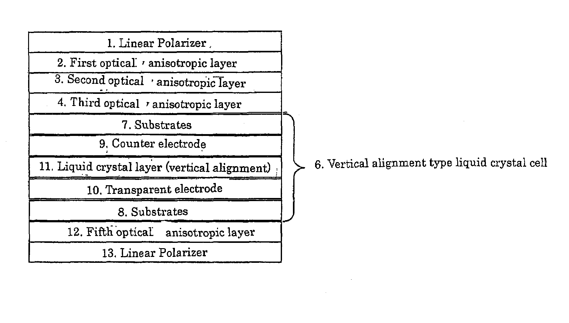
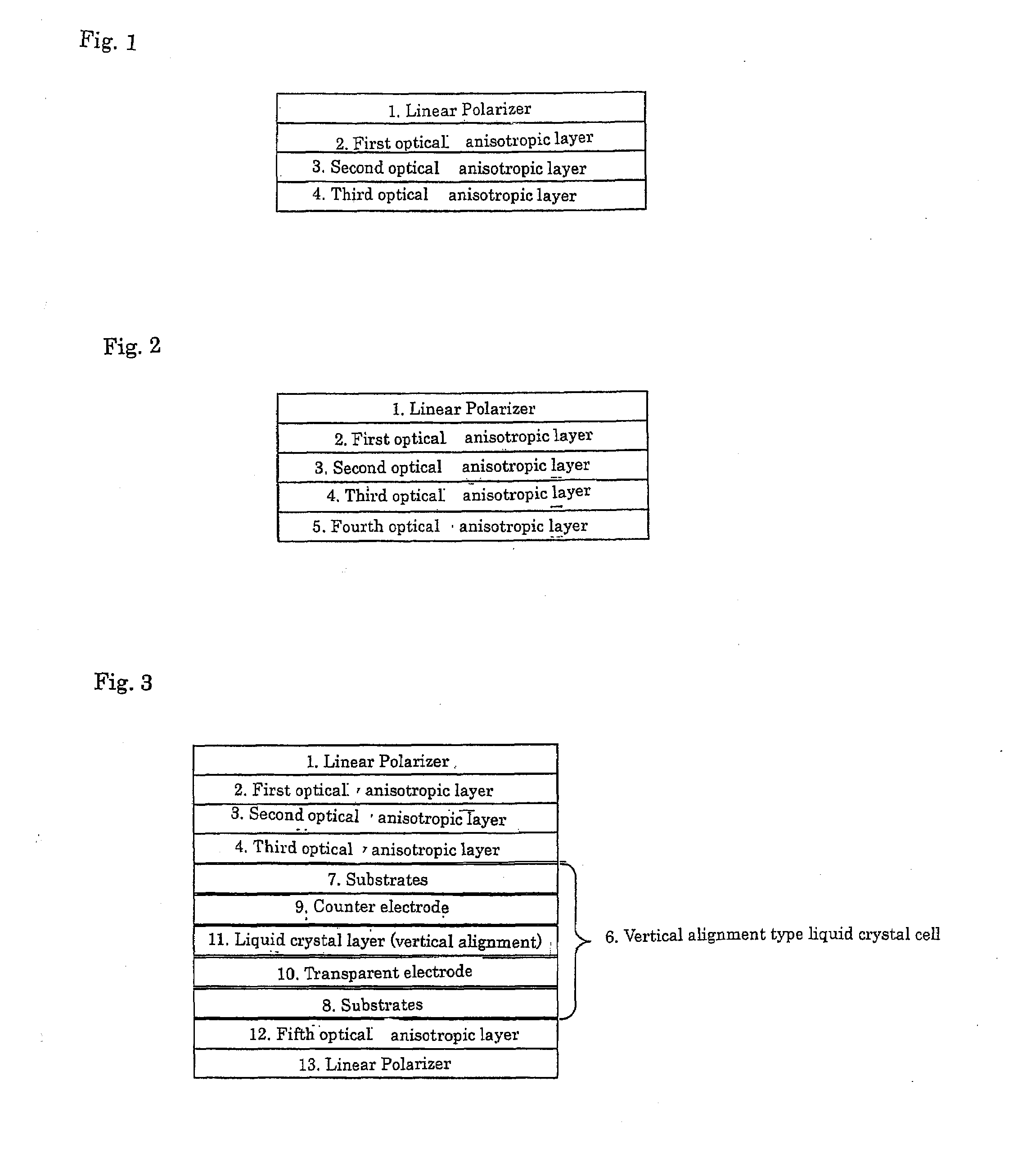
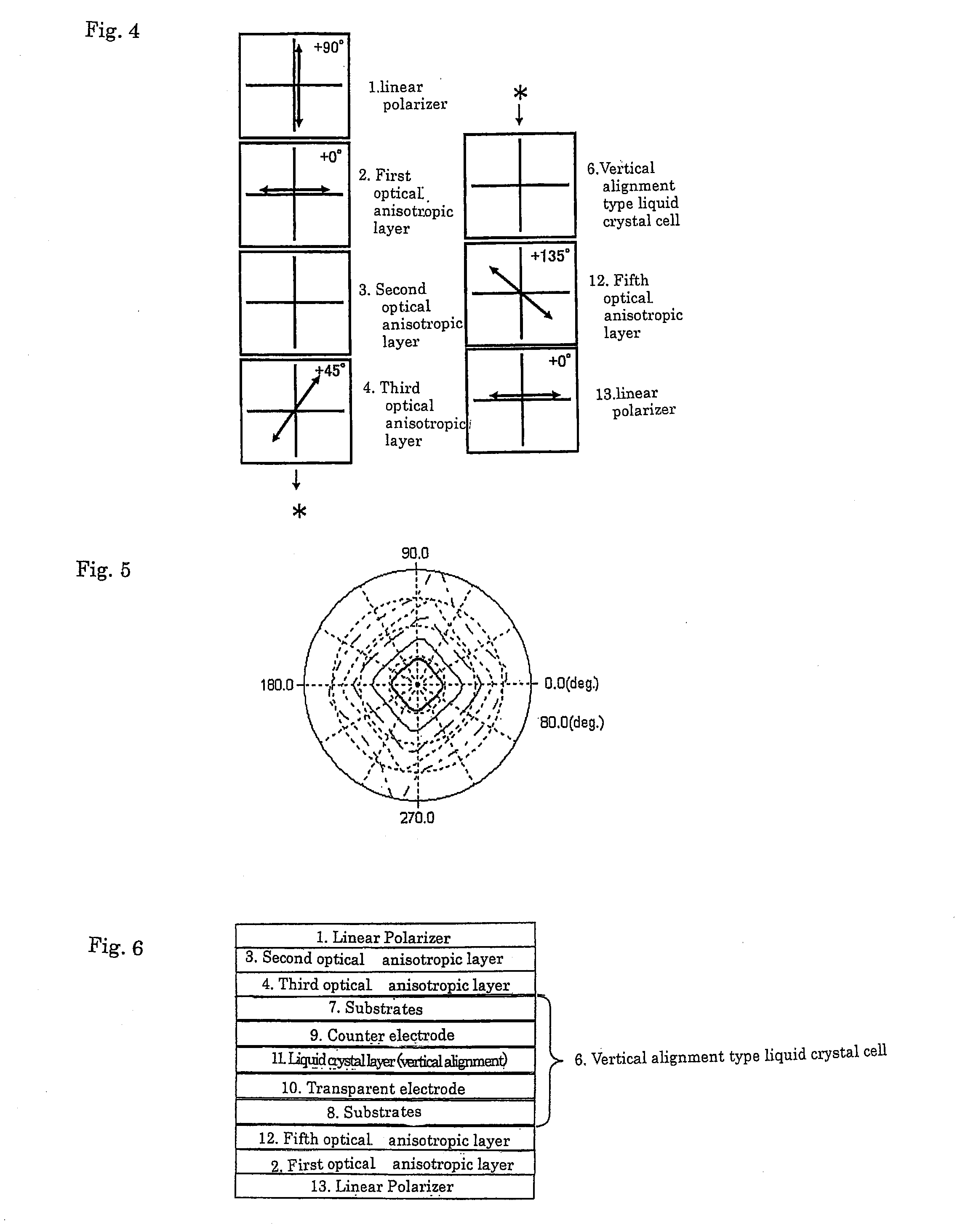
An elliptical polarizer with excellent viewing angle characteristics is provided which comprises at least a first polarizer, a first optical anisotropic layer, a second optical anisotropic layer, and a third optical anisotropic layer, laminated in this order, wherein the first optical anisotropic layer satisfies [1] 50≦Re1≦500, the second optical anisotropic layer satisfies [2] 0≦Re2≦20 and [3]−500≦Rth2≦−30, and the third optical anisotropic layer satisfies [4] 100≦Re 3≦180 wherein Re and Rth indicate the retardation values in the plane and thickness direction, respectively, of each of the optical anisotropic layers.

Description

FIELD OF THE INVENTION[0001]The present invention relates to elliptical polarizers with excellent viewing angle characteristics and liquid crystal display devices, in particular vertical alignment type liquid crystal display devices where liquid crystal molecules are aligned vertically with respect to a substrate when no electric voltage is applied.BACKGROUND OF THE INVENTION[0002]As one example of the display modes of a liquid crystal display device, there is a vertical alignment mode wherein the liquid crystal molecules in a liquid crystal cell are aligned vertically with respect to the substrates thereof under the initial conditions. When no electric voltage is applied, the liquid crystal molecules are aligned vertically with respect to a substrate. Therefore, a black image is obtained if linear polarizers are arranged in a orthogonal relation to one another on a liquid crystal cell.[0003]The optical characteristics in the liquid crystal cell is isotropic in the plane direction, ...

Claims


Application Information

Patent Timeline
IPC IPC(8): G02F1/1347G02B5/30G02F1/13
CPCG02B5/3033G02F1/13363G02F2001/133742G02F2413/06G02F2413/04G02F2413/05G02F2202/40G02F1/133742G02B5/30G02F1/1335
Inventor UESAKA, TETSUYAIKEDA, SATORU
Owner NIPPON OIL CORP
Learn More