Rotation detector and direct-current motor

Active Publication Date: 2010-02-11
DENSO CORP
View PDF5 Cites 39 Cited by
  • Summary
  • Abstract
  • Description
  • Claims
  • Application Information

AI Technical Summary

Benefits of technology

[0012]The invention has been made with the above problems taken into account. It is an object of the invention to provide a rotation detector capable of accurately detecting the rotational state of a direct-current moto

Problems solved by technology

However, this method of providing a sensor to detect a rotational state involves a problem.
This incurs increase in the weight and cost of the vehicle.
However, this method also involves a problem.
As the rotational speed is reduced, for this reason, it becomes more difficult to detect a surge pulse and the possibility of erroneous detection is increased.
However, the method disclosed in Patent Document 1 involves a problem.
In this method, a direct current passed through a motor circuit is caused to

Method used


Image

  • Rotation detector and direct-current motor
  • Rotation detector and direct-current motor
  • Rotation detector and direct-current motor

Examples


first embodiment

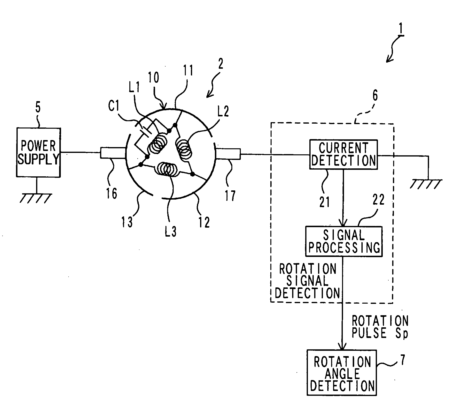
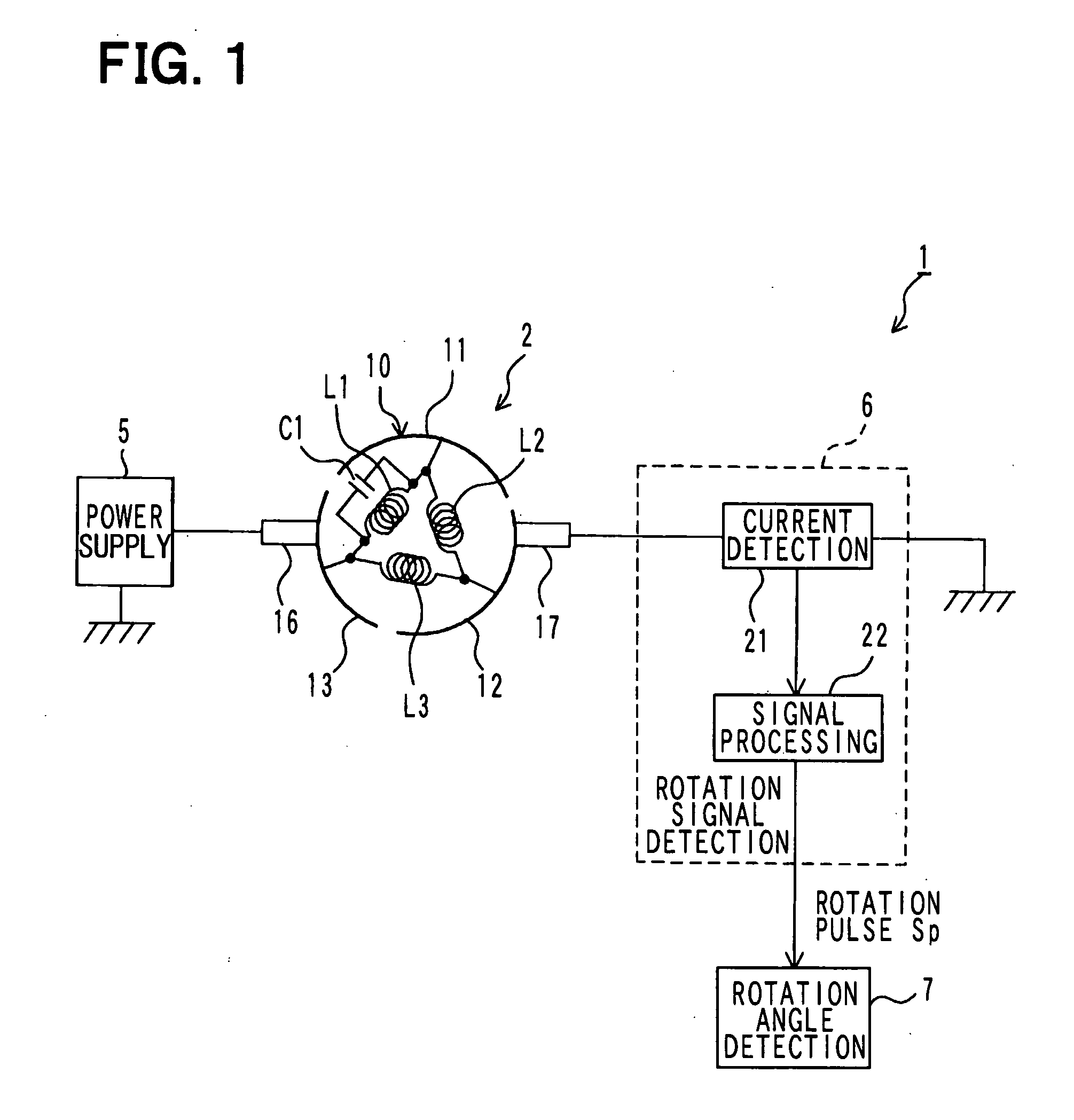
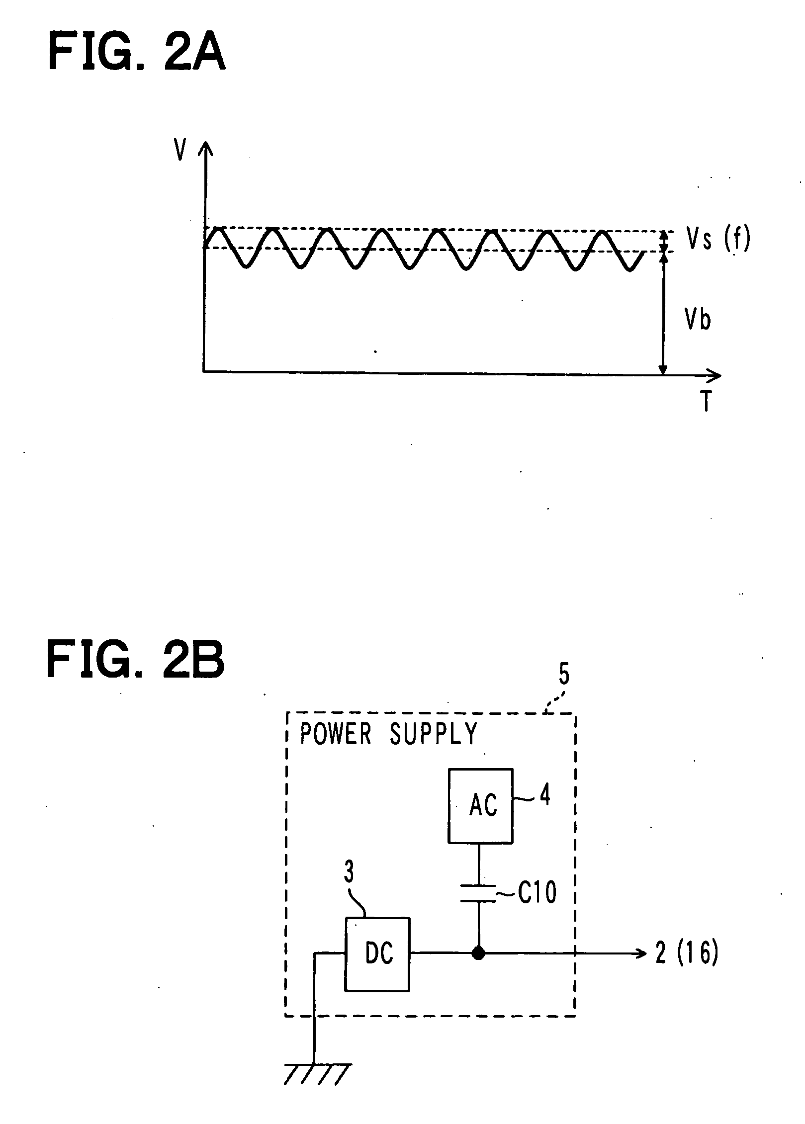
[0144]FIG. 1 illustrates the general configuration of a rotation angle detector in an embodiment of the invention. As illustrated in FIG. 1, the rotation angle detector 1 in this embodiment is a device for detecting the rotation angle of a motor 2. The rotation angle detector 1 includes a power supply unit 5 that outputs alternating current superimposed voltage obtained by superimposing alternating-current voltage of a predetermined frequency on direct-current voltage for causing the motor 2 to generate torque and rotationally driving the motor 2. In addition, the rotation angle detector 1 includes: a rotation signal detection unit 6 that generates and outputs a rotation pulse Sp as a signal corresponding to the rotation angle of the motor 2 based on motor current passed through the motor 2; and a rotation angle detection unit 7 that detects the rotation angle of the motor 2 based on the rotation pulse Sp outputted from this rotation signal detection unit 6.

[0145]The rotation angle ...

second embodiment

[0222]FIG. 8 illustrates the general configuration of a rotation detector 40 in this embodiment. As illustrated in FIG. 8, the rotation detector 40 in this embodiment includes: the motor 2; a power supply unit 33 that supplies power to this motor 2; the current detection unit 21 that detects a motor current passed through the motor 2; a signal processing unit 43 that generates a rotation pulse Sp based on the motor current detected by this current detection unit 21; and a control unit 41 that controls the power supply unit 33 and the signal processing unit 43.

[0223]The power supply unit 33 is identical with the power supply unit 5 in the first embodiment in that it includes the direct-current power source 3, alternating-current power source 4, and coupling capacitor C10. However, the power supply unit 33 in this embodiment is additionally provided with a direct-current power switch 34 located on the energization path extending from the direct-current power source 3 to the motor 2. S...

third embodiment

[0255]FIG. 10 illustrates the general configuration of a rotation angle detector 50 in this embodiment. As illustrated in FIG. 10, the rotation angle detector 50 in this embodiment is different from the rotation detector 40 in the second embodiment illustrated in FIG. 8 mainly in that power is supplied from the power supply unit 33 to the motor 2 through a motor driver 51. The other regards with respect to the configuration are basically the same as those in the rotation detector 40 in the second embodiment. For this reason, the same constituent elements as in the rotation detector 40 in the second embodiment will be marked with the same reference numerals as in the second embodiment and the detailed description thereof will be omitted.

[0256]The motor driver 51 is comprised of a publicly known H-bridge circuit comprising four switches. The H-bridge circuit is also designated as full-bridge circuit.

[0257]More specific description will be given. The motor driver 51 includes a switch T...


PUM


Abstract

A power supply unit superimposes alternating-current voltage on direct-current voltage and applies it to a motor. As a result, when the motor is rotated, a current containing an alternating-current component flows. Further, the motor includes a capacitor connected in parallel with one phase coil. Owing to this capacitor, the impedance of the motor circuit between brushes is varied according to the rotation of the motor. Variation in impedance appears as variation in the amplitude of the alternating-current component in motor current. A signal processing unit extracts an alternating-current component from the motor current detected by the current detection unit and generates a rotation pulse corresponding to variation in the amplitude. A rotation angle detection unit detects the rotation angle of the motor based on this rotation pulse.

Description

CROSS REFERENCE TO RELATED APPLICATION[0001]This application is based on Japanese Patent Application No. 2008-203112 filed on Aug. 6, 2008, and Japanese Patent Application No. 2009-141437 filed on Jun. 12, 2009, the contents of which are incorporated herein by reference in its entirety.FIELD OF THE INVENTION[0002]The present invention relates to a rotation detector that detects the rotational state, such as rotation angle, rotation direction, and rotational speed, of a brushed direct-current motor and a brushed direct-current motor whose rotational state can be detected with this rotation detector.BACKGROUND OF THE INVENTION[0003]Brushed direct-current motors (hereafter, simply referred to as “direct-current motors”) have been conventionally used in vehicles as well. They are used to adjust, for example, the opening angle of an air mix damper for temperature adjustment or a mode damper for mode selection in a vehicle air conditioner. To control a direct-current motor used in these a...

Claims


Application Information

Patent Timeline
IPC IPC(8): H02K11/00H02K23/00G01B7/30G01P3/481H02P7/06
CPCG01B7/30G01D5/2006G01P3/48H02P7/0094H02P6/185H02P2203/03H02K23/66
Inventor TANAKA, KENNAKAMURA, TSUTOMUTAKEDA, KENJITOUGE, MASARUFUKAGAWA, YASUHIRO
Owner DENSO CORP
Why Eureka
Try Eureka