
Radiation image conversion panel, its manufacturing method, and x-ray radiographic system

Active Publication Date: 2010-02-11
KONICA MINOLTA MEDICAL & GRAPHICS INC
View PDF6 Cites 20 Cited by
  • Summary
  • Abstract
  • Description
  • Claims
  • Application Information

AI Technical Summary

Benefits of technology

[0025]The constitution as described above of the invention can provide a radiation image conversion panel, which provides high luminance, an image without white or black defects, an image free from cracks, and an image with reduced unevenness and its manufacturing method, and can provide an X-ray radiographic system employing the radiation image conversion panel.BRIEF EXPLANATION OF THE DRAWINGS
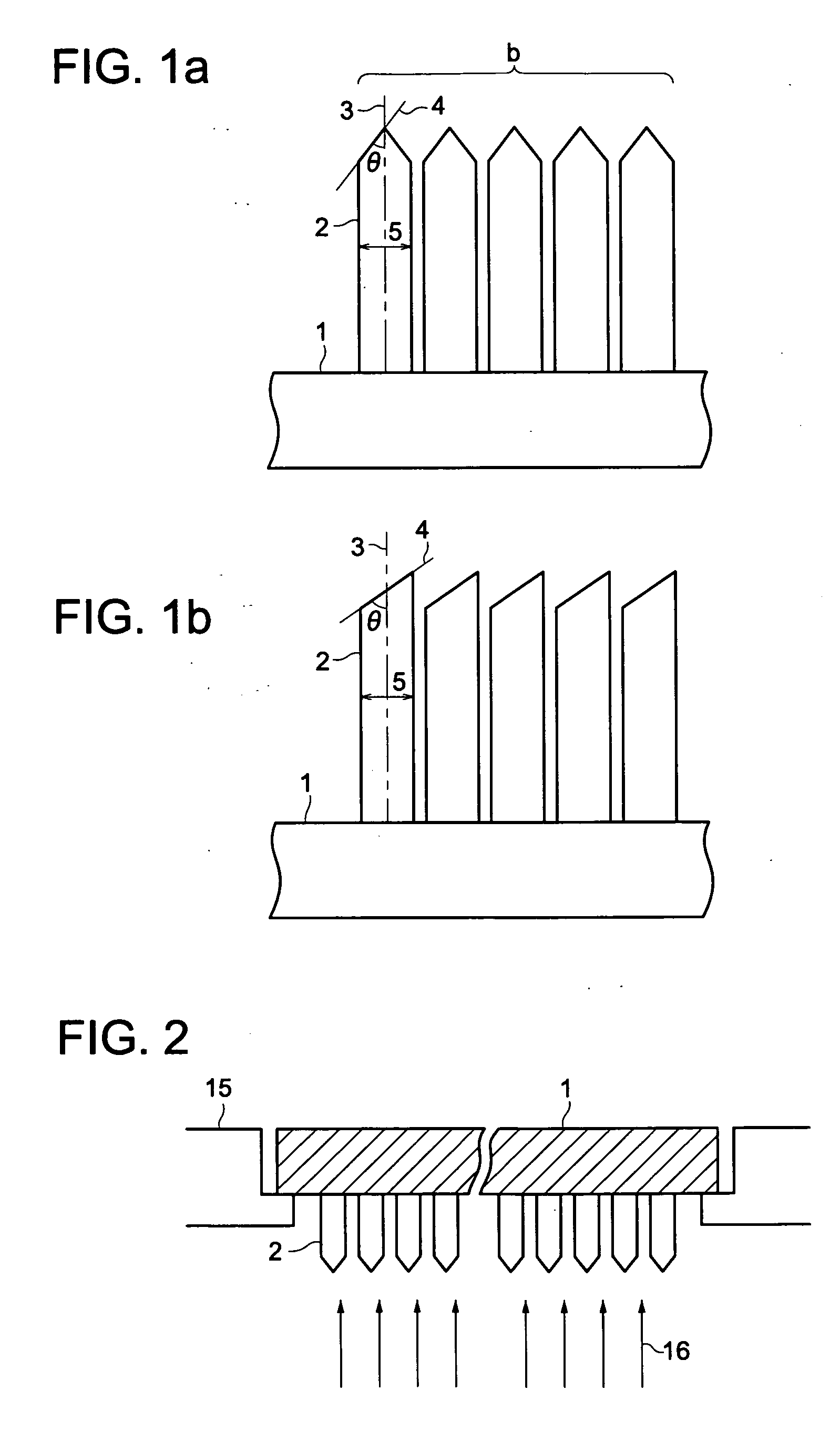
[0026]FIGS. 1a and 1b each are a schematic diagram showing one example of shapes of column crystals formed on a substrate.
[0027]FIG. 2 is a schematic diagram showing one example forming a stimulable phosphor layer on a substrate via vapor deposition.
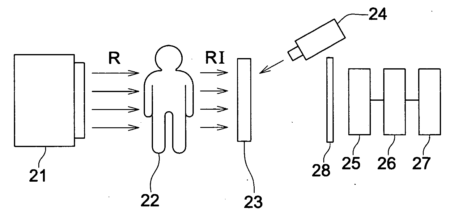
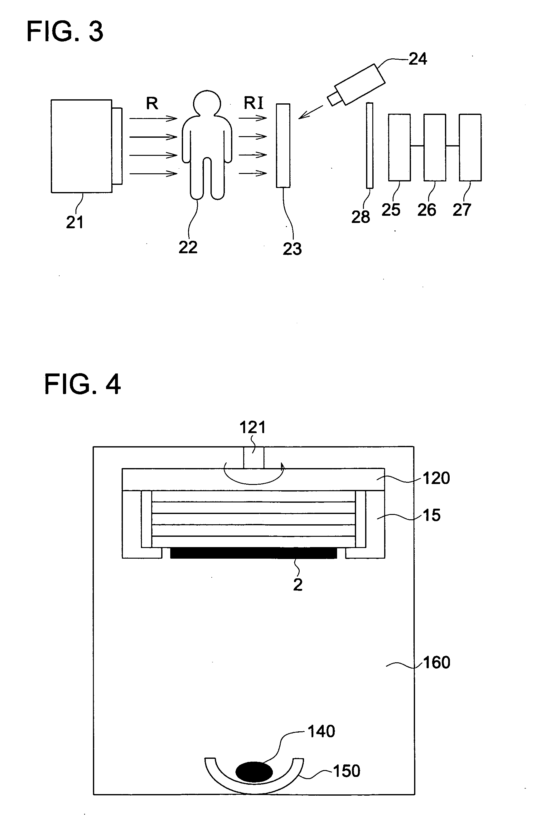
[0028]FIG. 3 is a schematic diagram showing one example of the configuration of a radiation image conversion panel and a radiation image reading apparatus.
[0029]FIG. 4 is a sectional diagram showing structure of one example of a vapor deposition apparatus.EXPLANATION OF THE NUMERICAL NUMBERS
[0032]3: Centerline passing through the center in the direction of crystal growth

Problems solved by technology

However, generally, a substrate for manufacturing a radiation image conversion panel has a large area (for example, 100×100 mm or larger), and is thin as compared with the size.
When the substrate is supported with a support in a vapor deposition apparatus for deposition of a stimulable phosphor, the substrate sags downwards in the center under its own weight, and therefore, there is problem in that it is difficult to form a uniform stimulable phosphor layer on the substrate.
However, the radiation image conversion panel as proposed above improves image quality to some level, but the improvement is still insufficient.
There are problems in a single metal layer that many defects are likely to occur, and defects such as density irregularity unevenness in an image are likely to be produced.

Method used


Image

  • Radiation image conversion panel, its manufacturing method, and x-ray radiographic system
  • Radiation image conversion panel, its manufacturing method, and x-ray radiographic system
  • Radiation image conversion panel, its manufacturing method, and x-ray radiographic system

Examples


examples

[0167]Next, the present invention will be explained employing examples, but is not specifically limited thereto.

>

[0168]A reflection layer with an intended thickness was provided on a substrate with a size of 100 cm×100 cm adhered to a metal block, employing a target of aluminum, silver, nickel or chromium as shown in Table 1 and a sputtering apparatus. When two kinds of targets are used, one target is exchanged to the other during formation of a protective layer so as to obtain half the thickness of the protective layer from each target. When an alloy protective layer is formed, a target employing two kinds of metals is provided, and subjected to simultaneous sputtering. The materials above are subjected to sputtering treatment to form a protective layer. After that, a solution in which polyester resin is dissolved in methyl ethyl ketone is coated on the protective layer via a spin coater, and dried at 100° C. for 10 hours in a thermostat to form a subbing layer.

[0169]Each of the re...


PUM


Abstract

Disclosed are a radiation image conversion panel, which provides high luminance, an image without white or black defects, an image free from cracks and an image with reduced unevenness, and its manufacturing method. Also disclosed is an X-ray radiographic system employing the radiation image conversion panel. The radiation image conversion panel of the invention comprises a substrate and provided thereon, a reflection layer, a phosphor layer and a protective layer in that order, wherein the phosphor layer is composed of a phosphor crystal in the form of column, and the reflection layer is formed by vapor phase deposition of two or more kinds of metals.

Description

FIELD OF THE INVENTION[0001]The present invention relates to a radiation image conversion panel, its manufacturing method, and an X-ray radiographic system employing the radiation image conversion panel.TECHNICAL BACKGROUND[0002]Radiographic images such as X-ray images are employed in many fields, for example, for use in diagnosis of an illness. There have been employed, as a method for obtaining X-ray images, so-called radiation photography systems in which X-rays which have passed through an object are irradiated onto a phosphor layer (fluorescent screen) to form a visible light, which is irradiated onto a silver halide photographic material (hereinafter, also denoted simply as a photographic material) similarly to conventional photography, followed by being subjected to photographic processing to obtain a visible silver image.[0003]Recently, there has been disclosed a new method for obtaining an image directly from a phosphor layer in place of an image forming method by use of si...

Claims


Application Information

Patent Timeline
IPC IPC(8): G01N23/04H05B33/02B05D5/06
CPCA61B6/00A61B6/4216G21K2004/06G21K4/00C09K11/7792
Inventor YANAGITA, TAKAFUMIARIMOTO, TADASHI
Owner KONICA MINOLTA MEDICAL & GRAPHICS INC
Features
  • Generate Ideas
  • Intellectual Property
  • Life Sciences
  • Materials
  • Tech Scout
  • Unparalleled Data Quality
  • Higher Quality Content
  • 60% Fewer Hallucinations
Learn More