
Cooled airfoil and method for making an airfoil having reduced trail edge slot flow

Inactive Publication Date: 2010-02-11
GENERAL ELECTRIC CO
View PDF20 Cites 12 Cited by
  • Summary
  • Abstract
  • Description
  • Claims
  • Application Information

AI Technical Summary

Benefits of technology

[0008]A first aspect of the present invention includes an airfoil component having a body having a leading edge and a trailing edge. The component includes an internal cooling passageway and an elongated opening in communication with the internal cooling passageway. The opening is configured with a geometry that provides structural stability during casting and has a cross-section that sufficiently restricts airflow through the opening to provide efficient component operation.
[0009]Another aspect of the present invention includes a gas turbine engine component casting insert having a ceramic insert body. The insert further includes core insert projections extending from the body having outer edge projections connected by a web portion. The outer edge projections have a thickness along the web portion that is greater than the thickness of the web portion. The core insert projections and web portion have sufficient structural stability to permit casting around the insert.
[0010]Still another aspect of the present invention includes a method for casting a gas turbine engine component. The method includes providing a core insert having core insert projections with outer edge projections connected by a web portion. The outer edge projections have a thickness along the web portion that is greater than the thickness of the web portion. A gas turbine engine component is cast over the core insert. The core insert is then removed to provide a gas turbine engine having cooling passages and elongated openings in communication with the cooling passages. The opening formed from removal of the core insert have a geometry that sufficiently restricts airflow through the opening to provide efficient component operation.
[0011]An advantage of an embodiment of the present invention is that the amount of bleed air from the compressor may be reduced and gas turbine engine operation may be more efficient.
[0012]Another advantage of an embodiment of the present invention is that the reduced cooling flow of cooling fluid from the trailing edge reduces or eliminates the need for other fluid flow restrictions, such as root plates.

Problems solved by technology

Without cooling, turbine blades would rapidly deteriorate.
Diverting any portion of the compressor air from use in the combustor necessarily decreases the overall efficiency of the engine.
This presents the challenge of making the core sturdy enough to survive the pouring of the metal while maintaining the stringent requirements for positioning the core.
The root plate undesirably increases manufacturing costs and provides additional maintenance costs by requiring the installation of an additional component adjacent the turbine component.

Method used


Image

  • Cooled airfoil and method for making an airfoil having reduced trail edge slot flow
  • Cooled airfoil and method for making an airfoil having reduced trail edge slot flow
  • Cooled airfoil and method for making an airfoil having reduced trail edge slot flow

Examples


Embodiment Construction

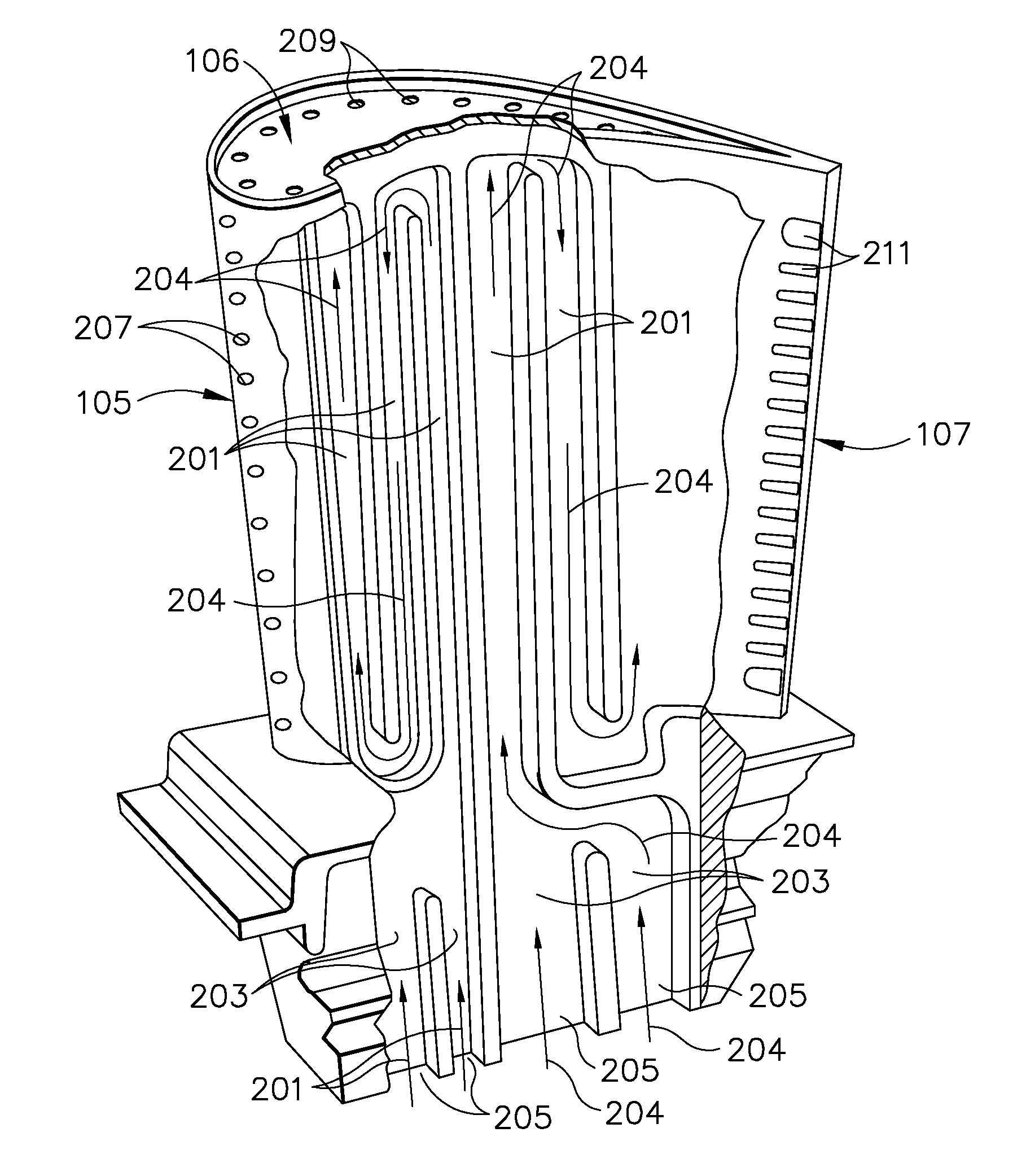
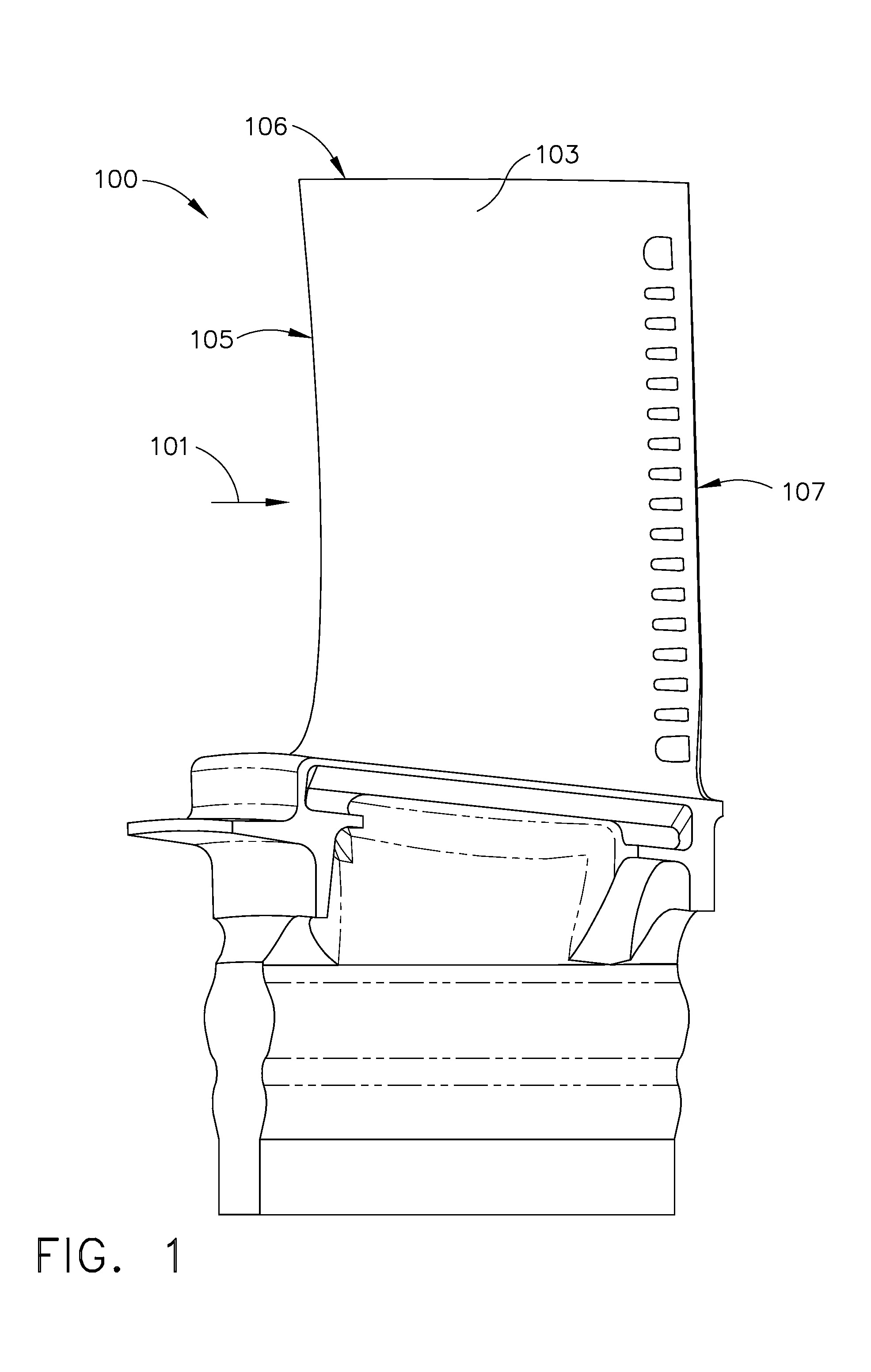
[0024]Illustrated in FIG. 1 is an exemplary turbine blade 100 for a gas turbine engine designed to be operated in a hot gas stream that flows in an axial flow downstream direction. During operation of the blade 100, combustion gases 101 are generated by a combustor (not shown) and flow downstream over the airfoil 103. The blade 100 includes a hollow airfoil 103 and a conventional root 104 used to secure the blade 100 to a rotor disk (not shown) of the gas turbine engine. The airfoil 103 includes an upstream leading edge 105, tip 106 and a downstream trailing edge 107 which is spaced chordally apart from the leading edge 105. The airfoil 103 extends longitudinally in a radial direction away from the root 104.

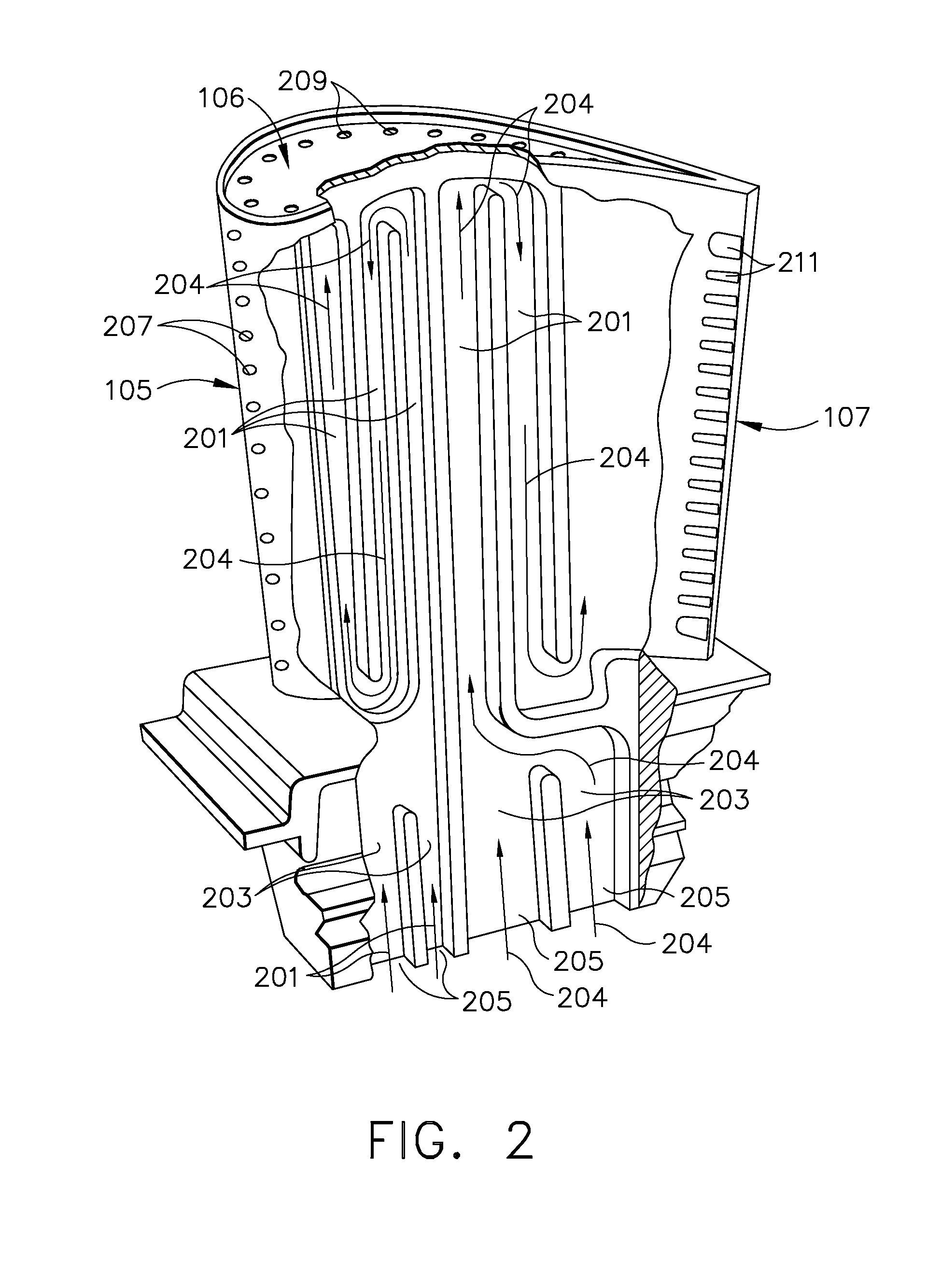
[0025]As shown in FIG. 2, the airfoil 101 includes an internal serpentine cooling circuit having cooling passages 201 traversing the hollow portions of airfoil 103. The configuration of cooling passageways 201 is not particularly limited and may include a plurality of circuits 20...


PUM

PropertyMeasurementUnit
Fractionaaaaaaaaaa
Fractionaaaaaaaaaa
Thicknessaaaaaaaaaa

Abstract

An airfoil component having a body having a leading edge and a trailing edge, a ceramic casting insert for making the component and the method for making the component. The component includes an internal cooling passageway and an elongated opening in communication with the internal cooling passageway. The opening is configured with a geometry that provides structural stability during casting and has a cross-section that sufficiently restricts airflow through the opening to provide efficient component operation. The casting insert includes outer edge projections and a web portion corresponding to the geometry of the openings when cast around the insert. The method includes casting the airfoil component around the casting insert and removing the insert to provide the component having the openings.

Description

FIELD OF THE INVENTION[0001]The present invention relates generally to gas turbine engine components, and more particularly to internally cooled airfoils used in gas turbine engine components.BACKGROUND OF THE INVENTION[0002]Temperatures within gas turbines may exceed 3000° F. (1650° C.), and cooling of turbine blades is very important in terms of blade longevity. The gas turbine engine operates by utilizing a compressor portion to compress atmospheric air to 10-25 times atmospheric pressure and adiabatically heating the air to between about 800°-1250° F. (427° C.-677° C.) in the process. This heated and compressed air is directed into a combustor, where it is mixed with fuel. The fuel is ignited, and the combustion process heats the gases to very high temperatures, in excess of 3000° F. (1650° C.). These hot gases pass through the turbine, where airfoils fixed to rotating turbine disks extract energy to drive the fan and compressor of the engine and the exhaust system, where the ga...

Claims


Application Information

Patent Timeline
IPC IPC(8): F01D5/18B23P15/02
CPCB22C9/10F01D5/081F01D5/187F05D2240/122F05D2240/304Y02T50/67Y10T29/49343F05D2230/21F05D2260/202F05D2260/2212F05D2260/22141F05D2260/2214Y02T50/676Y02T50/60
Inventor JENDRIX, RICHARD W.WILLIAMS, CORY
Owner GENERAL ELECTRIC CO
Learn More