Detuning circuit and detuning method for an MRI system

a technology of magnetic resonance imaging and detuning circuit, which is applied in the field of magnetic resonance imaging system, can solve the problems of degrading image quality, unstable biasing current, and inability to maintain the pin diode series resistance low enough, so as to facilitate robust forward biasing of the pin diode and fast reverse recovery time

a technology of magnetic resonance imaging and detuning circuit, which is applied in the field of magnetic resonance imaging system, can solve the problems of degrading image quality, unstable biasing current, and inability to maintain the pin diode series resistance low enough, so as to facilitate robust forward biasing of the pin diode and fast reverse recovery time

US20100039113A1Inactive Publication Date: 2010-02-18KONINKLIJKE PHILIPS ELECTRONICS NV

Image

  • Detuning circuit and detuning method for an MRI system
  • Detuning circuit and detuning method for an MRI system
  • Detuning circuit and detuning method for an MRI system

Examples


Embodiment Construction

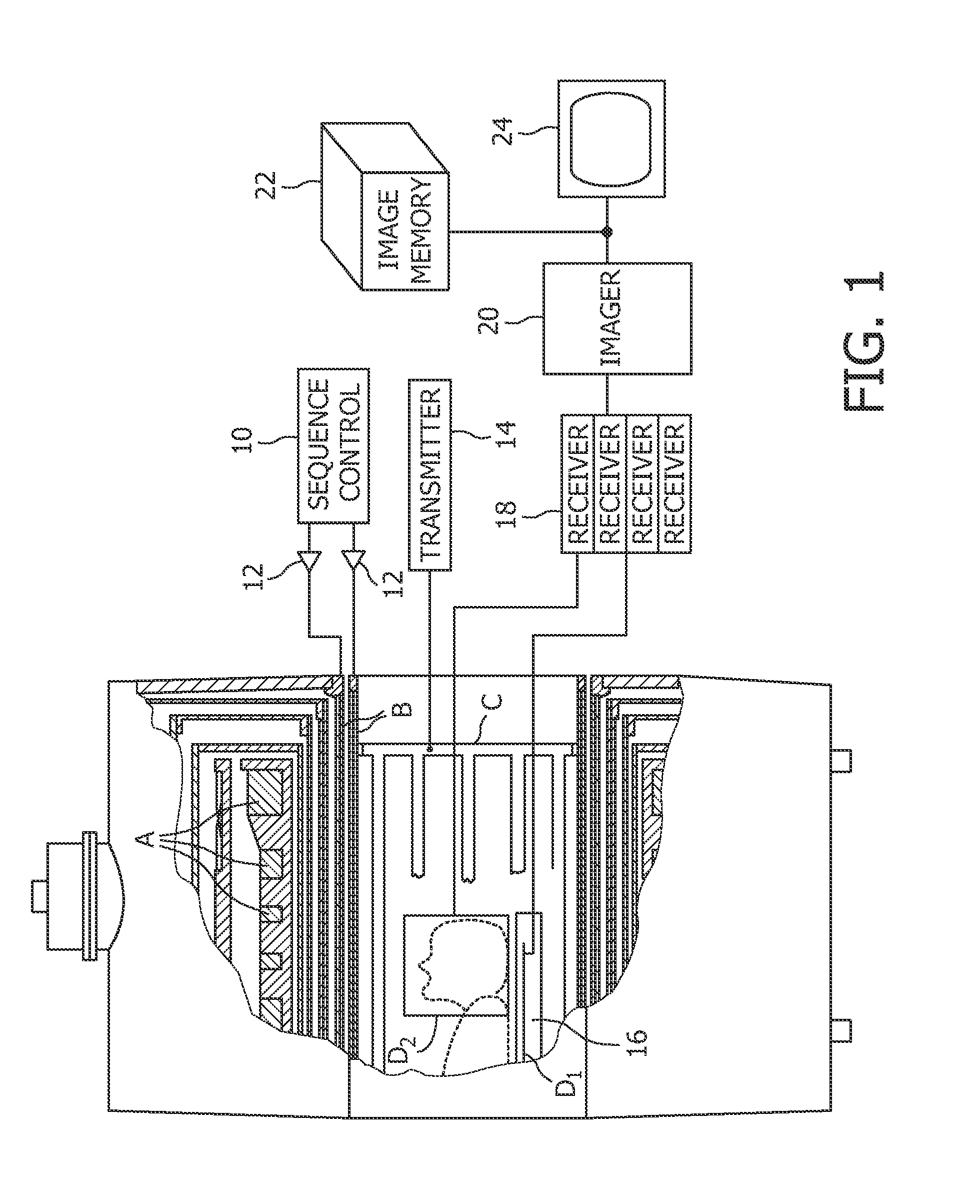
[0031]With reference to FIG. 1, a magnetic resonance imaging apparatus includes a main magnetic field generator A for establishing a temporally constant, main magnetic field B0 through an examination region. Gradient magnetic field coils B selectively produce magnetic field gradients transversely across the main magnetic field of the imaging region. An RF transmitter coil C, selectively transmits radio frequency resonance excitation and manipulation pulses during a transmit portion of each transmit / receive cycle. These high power excitation and manipulation pulses excite magnetic resonance in the nuclei of the subject disposed in the imaging region. The resonating nuclei generate radio frequency signals of a frequency which is determined by the strength of the magnetic field and other variables such as the specific nuclei targeted. A magnetic resonance imaging sequence controller 10 is functionally connected to drivers 12 for the gradient coils B and a transmitter 14 for driving the...


PUM


Abstract

The present invention relates to a magnetic resonance imaging system and a corresponding method having a transmit phase and a receive phase. Further, the present invention relates to a detuning circuit and a corresponding detuning method for detuning an RF receive coil during the transmit phase in such a magnetic resonance imaging system. In high-field MRI systems the transmit mode operating frequency is higher than normal high breakdown voltage rectifiers can handle when they are used to forward bias a passive detuning circuit PIN diode switch. The proposed circuit uses a current-limiting capacitor (C5) in series with a fast (e.g. schottky) rectifier diode (V2) with a reverse breakdown voltage of e.g. 20 volts and a fast reverse recovery time to generate a DC current. The rectifying circuit is isolated from the PIN diode (V1) with a relatively high-value inductor (L2), which ensures that no harmful transient current spikes can flow from the PIN diode anode to the rectifying circuit. The inductor (L2) still passes and maintains the DC current generated by the rectifying circuit through the PIN diode, thus enabling the robust forward-biasing of the PIN-diode during transmit mode. The use of a fast (and thus low-power) rectifier results in less dissipation on the detuning circuit, and helps in fulfilling the surface temperature limits posed on receiver coils.

Description

FIELD OF THE INVENTION[0001]The present invention relates to a magnetic resonance imaging system and a corresponding method having a transmit phase and a receive phase. Further, the present invention relates to a detuning circuit and a corresponding detuning method for detuning an RF receive coil during the transmit phase in such a magnetic resonance imaging system.BACKGROUND OF THE INVENTION[0002]Magnetic resonance imaging (MRI) devices apply a main magnetic field through an examination region. This strong field, typically denoted B0, acts to align the nuclei within a subject to be examined. In some MRI devices, the B0 field is horizontally oriented, and in others it is vertically oriented.[0003]In both horizontally and vertically oriented systems, magnetic resonance is excited in the aligned nuclei by a relatively strong orthogonal RF (radio frequency) field, typically denoted B1. The B1 field causes the aligned nuclei or spins to tip into a plane orthogonal to the static magnetic...

Claims


Application Information

Patent Timeline
18 Feb 2010
Publication
US20100039113A1
IPC
G01R33/36
CPC
G01R33/3657
Inventors
VARTIOVAARA, VILLE P.